3. The floor eyebolts should be already secured to the concrete floor. Verify the height of the center of
the floor eyebolt to the concrete floor or the steel beam/channel adapter mounted to the concrete
floor. Ensure that the turnbuckles can accommodate the total height of the raised floor.
4. Remove the floor tiles around the area where the frame(s) will be installed.
5. Remove the pin and the spacer from the lower jaw (see the following illustrations).
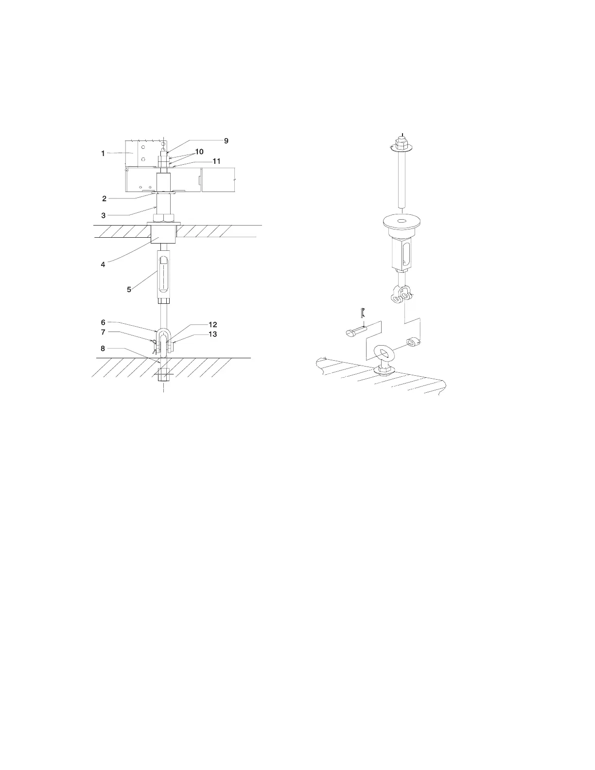
1 Frame 8 Floor Eyebolt (customer-supplied)
2 Jam Nut 9 Threaded Rod
3 Rack Leveler 10 Nut
4 Rubber Bushing 11 Washer
5 Turnbuckle (Short or Long) 12 Spacer
6 Lower Jaw 13 Shaft
7 Pin
Note: The difference between the two turnbuckle assemblies is the length of the turnbuckle.
The Short Turnbuckle Assembly (part number 11P4755) is used for a 9 1/2 inches to 11 3/4
inches raised floor.
The Long Turnbuckle Assembly (part number 11P4756) is used for an 11 3/4 inches to 16
inches raised floor.
6. Place the spacer inside the floor eyebolt and place the floor eyebolt between the lower jaw. Reinstall
the shaft, pin, and spacer.
7. Remove the threaded rod and rubber bushing from the turnbuckle assembly.
8. Install the floor tile that has the rubber bushing holes that are aligned with the eyebolt locations.
9. Install the rubber bushings in the floor tiles.
10. Move the frame so that the frame leveler is located over the rubber bushings.
Attention: To avoid a tipping hazard, make sure that the frame casters do not roll into the cable
opening.
Chapter 2. Physical Characteristics of Systems 191
 Loading...