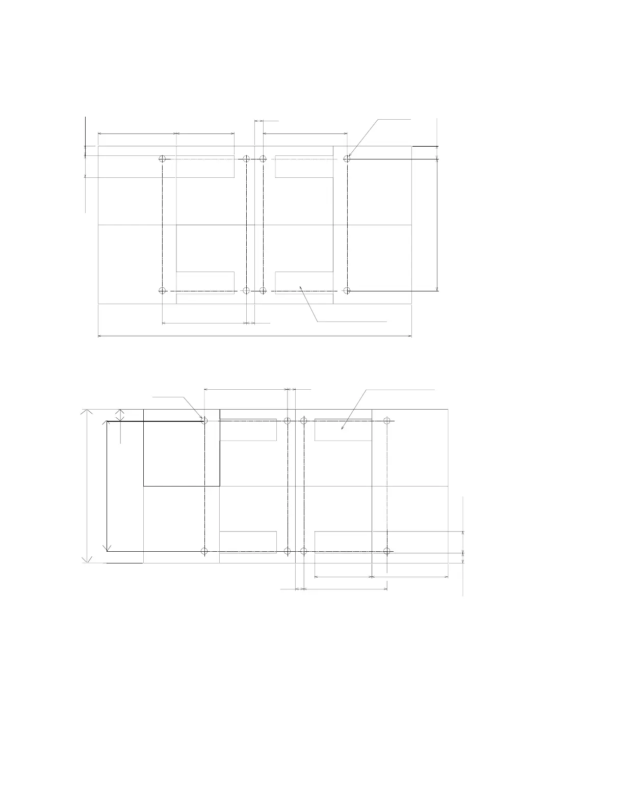
3. Plan for installing four eyebolts positioned to match the dimensions given in the following illustrations.
654.8 mm
654.8 mm
(4x) 450 mm REF
(8)x49.3mm
Eyebolts
(4X) 75 mm REF
610 mm REF
(4X) 170 mm REF
2440 mm REF
1019 mm
64.6 mm
64.6 mm
100.5 mm
24 Inch Floor Tile Layout
(4) Opening for Cables
24 in REF
96 in REF
(4X) Opening for Cables654.8 mm
(8) 49.3 mm
Eyebolt
654.8 mm
600 mm (23.6 Inch Floor) Tile Layout
600 mm REF
23.6 in REF
(4) 170 mm REF
1200 mm REF
47.2 in REF
1019 mm
90.5mm
(4)75mm
2.96 in
64.6 mm
64.6 mm
(4X) 450 mm REF
4. Install the eyebolts to the floor.
To install the frame, do the following:
Attention: It is the service representative’s responsibility to complete the following steps.
1. Before starting the installation, check all cable openings in the floor panel and location of the rubber
bushing holes so that they match the dimensions given in the illustrations on 190 and 190.
2. Power off the system and make sure all cables and connectors are disconnected and are not
dangling around the frame. The frame should be free to roll.
190 Site and Hardware Planning Information
 Loading...