12. Locate the memory DIMMs, and determine which DIMM you want to remove.
Note: Memory DIMMs must be installed in quads (groups of 4) and in the correct
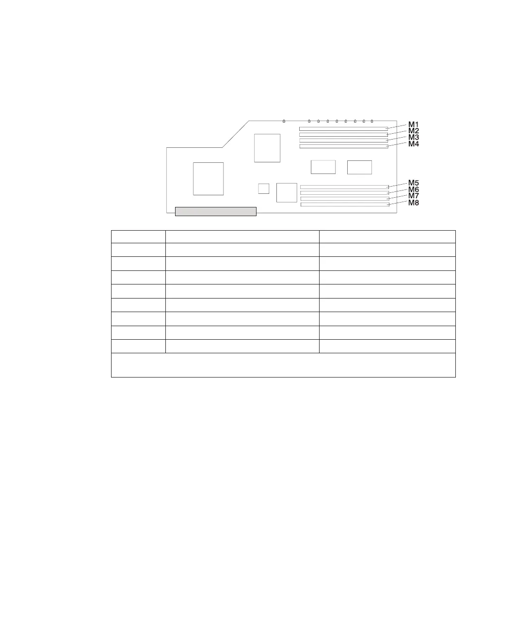
slot. The only two valid slot combinations that you can use are 1, 3, 6, and
8 or 2, 4, 5, and 7. See the following illustration.
Number Description Location Code
M1 Memory slot 1 (J2A) U0.1-P1-C1-M1
M2 Memory slot 2 (J2B) U0.1-P1-C1-M2
M3 Memory slot 3(J3A) U0.1-P1-C1-M3
M4 Memory slot 4(J3B) U0.1-P1-C1-M4
M5 Memory slot 5(J1B) U0.1-P1-C1-M5
M6 Memory slot 6(J1A) U0.1-P1-C1-M6
M7 Memory slot 7(J0B) U0.1-P1-C1-M7
M8 Memory slot 8(J0A) U0.1-P1-C1-M8
Note: The location code column in this table is showing the location codes for processor card 1.
If your system is configured for processor card 2, substitute C2 in place of C1.
Attention: To prevent damage to the memory DIMM and the memory DIMM
connectors, open or close the retention latches at the same time.
13. Remove the memory DIMM by pushing the tabs out and then down. The tabs’
camming action forces the memory DIMM out of the connector.
116 Eserver
pSeries 630 Model 6C4 and Model 6E4 Installation Guide
 Loading...


