Table 7. Memory mirrored channel mode DIMM population sequence (continued)
Number of DIMMs
Number of installed
microprocessor DIMM connector
Table note: DIMM connectors 3, 6, 7, 10, 15, 18, 19, and 22 are not used in memory
mirrored channel mode when UDIMMs are installed in the server.
Memory rank sparing
The memory rank sparing feature disables the failed memory from the system
configuration and activates a rank sparing DIMM to replace the failed active
DIMM.
You can enable rank sparing memory in the Setup utility, select System Settings >
Memory. For more information, see “Using the Setup utility” on page 106.
The maximum available memory is reduced when memory rank sparing mode is
enabled.
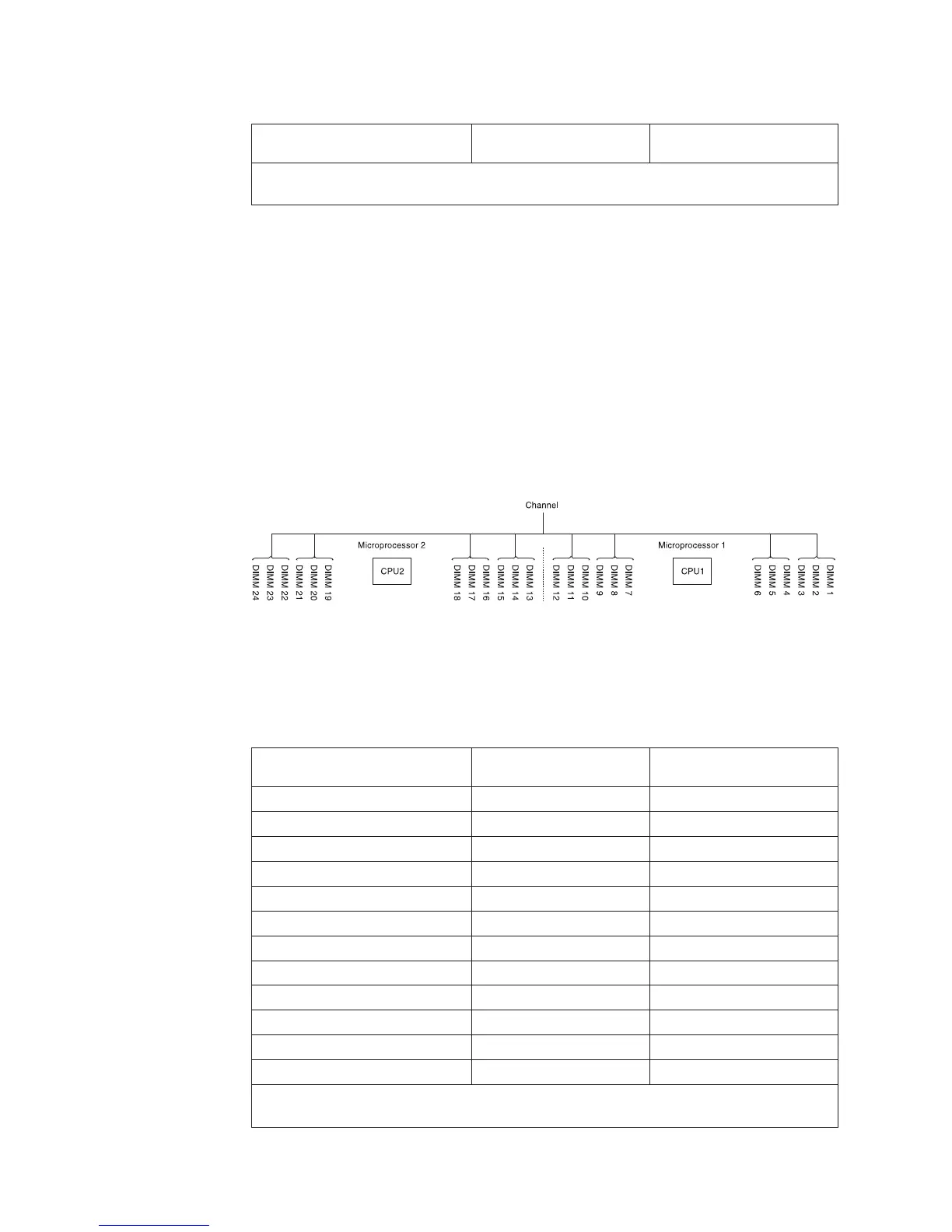
The following diagram lists the DIMM connectors on each memory channel.
Follow the installation sequence for rank sparing mode:
v Install at least one quad-rank DIMM in a channel.
v Install at least two single-rank or dual-rank DIMMs in a channel.
Table 8. Memory rank sparing mode DIMM population sequence
Number of DIMMs
Number of installed
microprocessor DIMM connector
First pair of DIMMs 1 1, 2
Second pair of DIMMs 1 4, 5
Third pair of DIMMs 1 8, 9
Fourth pair of DIMMs 1 11, 12
Fifth pair of DIMMs 1 7, 10
Sixth pair of DIMMs 1 3, 6
Seventh pair of DIMMs 2 13, 14
Eighth pair of DIMMs 2 16, 17
Ninth pair of DIMMs 2 20, 21
Tenth pair of DIMMs 2 23, 24
Eleventh pair of DIMMs 2 19, 22
Twelfth pair of DIMMs 2 15, 18
Table note: DIMM connectors 3, 6, 7, 10, 15, 18, 19, and 22 are not used in memory rank
sparing mode when UDIMMs are installed in the server.
Figure 37. Connectors on each memory channel
54 IBM System x3550 M4 Type 7914: Installation and Service Guide
 Loading...


