About this task
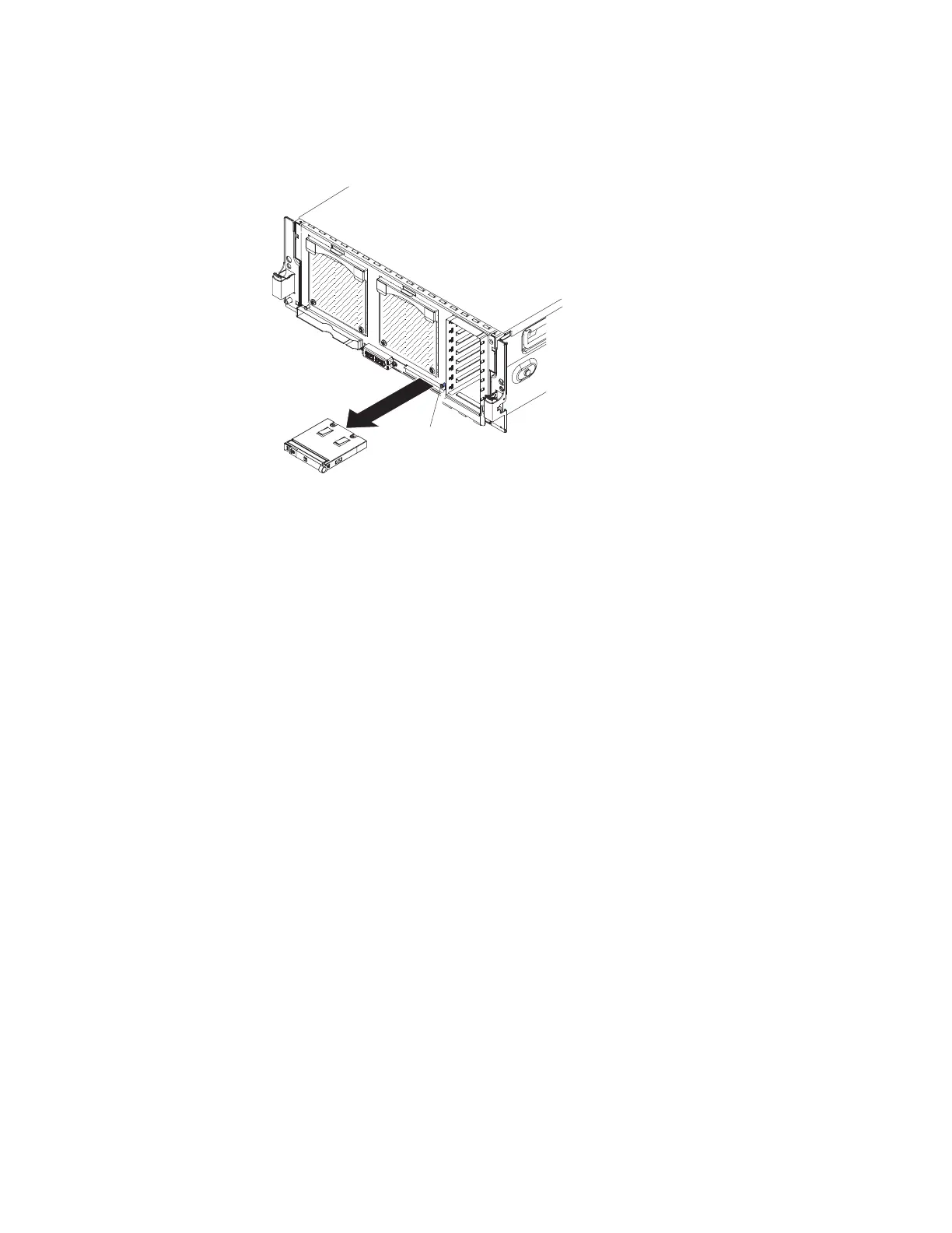
To remove the operator information panel assembly, complete the following steps.
Release
latch
Procedure
1. Read the safety information that begins with “Safety” on page v and
“Installation guidelines” on page 97.
2. Turn off the server and peripheral devices, and disconnect the power cords and
all external cables as necessary to replace the device.
3. Remove the front bezel and the top cover (see “Removing the front bezel” on
page 108 and “Removing and replacing consumable parts and Tier 1 CRUs” on
page 105).
4. Remove the memory cards or fillers from slots 5, 6, 7, and 8 (see “Removing a
memory card” on page 136).
5. Disconnect the operator information panel (front panel) cable from the
microprocessor board, see “Microprocessor-board connectors” on page 24.
6. Press the blue release button above the assembly and carefully pull the
assembly out of the server. Make sure that you do not damage the cable as you
remove the assembly from the server.
7. Disconnect the cable from the rear of the operator information panel.
8. If you are instructed to return the operator information panel assembly, follow
all packaging instructions, and use any packaging materials for shipping that
are supplied to you.
Chapter 5. Removing and replacing components 119
 Loading...


