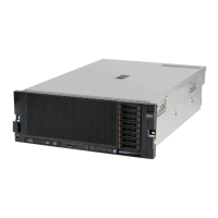
Replacing the operator information panel assembly
This topic provides instructions for how to install the replacement operator
information panel assembly.
About this task
To install the replacement operator information panel assembly, complete the
following steps:
Procedure
1. Connect the operator information panel cable to the rear of the new operator
information panel.
2. Thread the operator information panel cable into the operator information
panel bay and insert the assembly into the server from the front.
3. Connect the cable to the microprocessor board.
4. Install the memory cards or fillers in slots 5, 6, 7, and 8 (see “Replacing a
memory card” on page 137).
5. Install the front bezel and the top cover (see “Replacing the front bezel” on
page 109 and “Replacing the top cover” on page 107).
6. Connect the cables and power cords (see “Connecting the cables” on page 104
for cabling instructions).
7. Turn on all attached devices and the server and check the server for normal
operation.
Removing the front hot-swap fans
This topic provides instructions for how to remove a front hot-swap fan.
About this task
To remove a front hot-swap fan, complete the following steps:
Procedure
1. Read the safety information that begins with “Safety” on page v and
“Installation guidelines” on page 97.
2. Remove the front bezel.
120 IBM System x3850 X5 and x3950 X5 Types 7145, 7146, 7143, and 7191: Problem Determination and Service Guide

 Loading...