Replacing the memory expansion module five-drop fan cable
assembly
This topic provides instructions for how to install the five-drop fan cable assembly.
About this task
To install the five-drop fan cable assembly, complete the following steps:
Procedure
1. Read the safety information that begins with “Safety” on page v and
“Installation guidelines” on page 97.
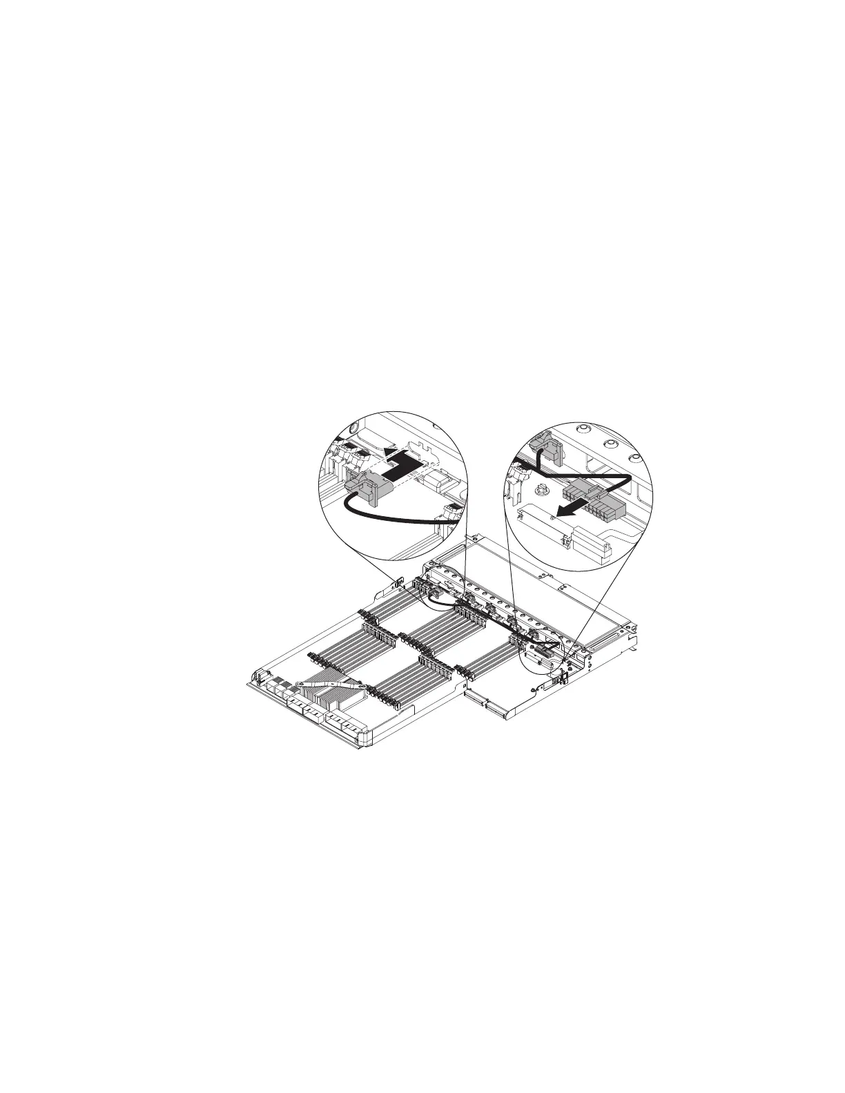
2. Connect the five-drop fan cable connectors to the rear of the fans, starting with
the fan that is farthest from the operator information panel.
3. Insert the fan cable connector into the connector on the system-board tray and
push it to the left to lock it in place; then route that fan cable through the cable
clamp next to that fan. Repeat this for each fan connector until you have
connected all five fan connectors to the fan connectors in the fan cage and the
cable is routed through the clamps.
4. Connect the five-drop fan cable to the connector on the system board.
5. Replace the fans (see “Replacing a memory expansion module hot-swap fan”
on page 184
6. Replace the system-board tray (see “Removing the memory expansion module
system-board tray assembly” on page 197).
7. Replace the bezel (see “Replacing the memory expansion module bezel” on
page 178).
8. Reconnect the power cords to the memory expansion module; then, connect all
external cables to the memory expansion module.
9. Turn on the peripheral devices and the host server.
196 IBM System x3850 X5 and x3950 X5 Types 7145, 7146, 7143, and 7191: Problem Determination and Service Guide
 Loading...


