29
Select Loc’n of shunt pump?
MFR2 ()
MFR3 ()
MFR4 ()
Select Loc’n of shunt pump?
MFR3 ()
MFR4 ()
TheMasterboilerinacascadecanindicateif
asystemfaultconditionexists,soanyboiler
fault,MasterorSlave.Thiscanthenbeused
to indicate to plant monitoring equipment
if any fault exists in the complete system.
If this is required then select the output of
the Master boiler that controls this signal.
Otherwiseselect‘None’.
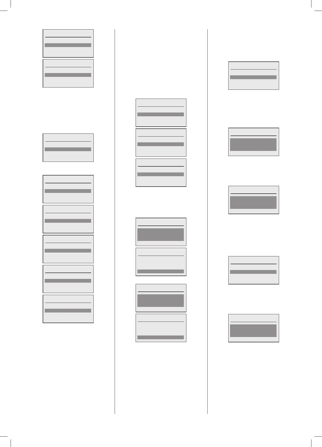
System fault indication
None
PWM/0-10V ()
MFR1 (HC1 pump)
Thefollowingoutputscanbeconguredfor
thisfunction:
System fault indication
None
PWM/0-10V ()
MFR1 (HC1 pump)
MFR2 (DHW pump)
System fault indication
PWM/0-10V ()
MFR1 (HC1 pump)
MFR2 (DHW pump)
MFR3 (Boiler on indicator)
System fault indication
MFR1 (HC1 pump)
MFR2 (DHW pump)
MFR3 (Boiler on indicator)
MFR4 (Boiler Fault Indicator)
System fault indication
MFR2 (DHW pump)
MFR3 (Boiler on indicator)
MFR4 (Boiler Fault Indicator)
System fault indication
MFR3 (Boiler on indicator)
MFR4 (Boiler Fault Indicator)
The plant may be controlled in a number
ofways:
1. 0-10V analogue input
2.230V50Hzswitchedliveinputviaa‘Volts
Free’contact
3.OpenThermMastercontroller
0-10V analogue input control
If the Plant cascade control is via a BMS
witha0-10Vsignalthenthiscanbeselected
andcongurednext.Thefollowingoptions
areavailable:
Congure 0-10V input
None
0-10V Capacity
0-10V Temperature
Congure 0-10V input
None
0-10V Capacity
0-10V Temperature
Congure 0-10V input
0-10V Capacity
0-10V Temperature
If 0-10V Temperature control is selected,
then the parameters for the Minimum and
Maximumowtemperatureinrelationtothe
voltagedemandrangevaluescanbe
set.
0-10V input Temp. Setp. 0V:
Temp. setp. 0V
8
º
C
Done
Temp. setp. 0V
8
º
C
Done
0-10V input Temp. Setp. 10V:
Temp. setp. 10V
80
º
C
Done
Temp. setp. 10V
80
º
C
Done
Once 0-10V control is selected a number
ofparametersmustbedened.Thedefault
settingsareasshownbelowbutthesecan
be hanged if required. To configure the
parametersselect‘Yes’,toacceptthecurrent
defaultsettingsselect‘No’.
Congure 0-10V parameters
No
Yes
Once‘Yes’isselectedtheparameterscanbe
setusingthefollowingscreens.
Voltagedemand.Thissettingdeterminesthe
switchingpointatwhichdemandisexpected
bythesystem,anythingbelowthisisatkeep
alivevoltage:
Congure voltage demand
1.0V
Done
Voltage life zero. This setting determines
theminimumkeepalivevoltagewherethe
systemexpectsavoltagetobepresenton
anoperationalinterface,anythingbelowthis
indicatesawiringfault:
Congure voltage life zero
0.0V
Done
Once this level is set, ‘Done’ may be
selected.
The next plant control signal that may be
congurediswhereaSwitchedLivesignal
isusedtogenerateademandtoenablethe
cascade.
SL1 230V demand
Congure SL1
None
Enable
Ifthissignalistobeconguredthenselect
Enable,otherwiseselect‘None’.Thiswillthen
promptforaCascadeowtemperatureset
point,whichwillbethetargettemperaturefor
thecascadeunderdirectSL1control.
Plant Setp. SL1
85ºC
Done
Oncethislevelisset,‘Done’maybeselected.