31
5.4 Boiler Conguration
Thenextstageistocongureeachofthe
boilersinthecascade.Thisprocessiscarried
outfromtheMasterboiler.Theconguration
parametersfortheboilercongurationare
specictothatparticularboiler.
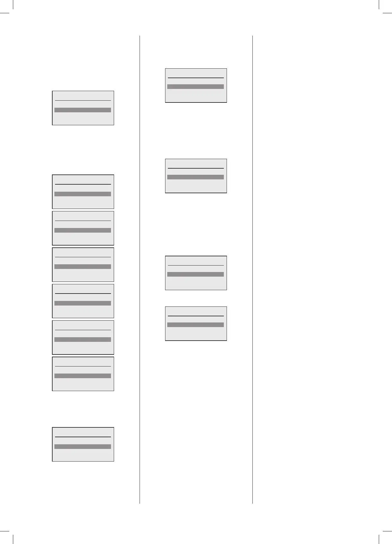
Selecttheboilerfromthelistwhichistobe
congured.
Select boiler to congure
Boiler1
Boiler 2
Done
If the selected boiler has its own unique
primary water circulation pump this is
where it is congured. Once again one of
the programmable outputs from the boiler
canbeusedtocontrolthispumpfunction.
Ifnoindividualboilerpumpispresentthen
select‘None’.
Select location of boiler pump
None
PWM/0-10V ()
MFR1 ()
Select location of boiler pump
None
PWM/0-10V ()
MFR1 ()
MFR2 ()
Select location of boiler pump
PWM/0-10V ()
MFR1 ()
MFR2 ()
MFR3 ()
Select location of boiler pump
MFR1 ()
MFR2 ()
MFR3 ()
MFR4 ()
Select location of boiler pump
MFR2 ()
MFR3 ()
MFR4 ()
Select location of boiler pump
MFR3 ()
MFR4 ()
The next boiler conguration step is the
Boiler On indication output. Once again
any of the programmable outputs may be
selected.UsuallyMFR3isallocated.Thefull
screens list is omitted for simplicity.
Boiler on indication
None
PWM/0-10V ()
MFR1 ()
The next boiler conguration step is the
Boiler Fault indication output. Once again
any of the programmable outputs may be
selected.UsuallyMFR4isallocated.Thefull
screens list is omitted for simplicity.
Boiler fault indication
None
PWM/0-10V ()
MFR1 ()
The next boiler configuration step is the
LPGvalvecontroloutput.Thisfunctionisfor
controlofanexternalLPGvalveinserieswith
theGaslineasanadditionalsafetyfeature.
Itis openedduringtheburner phase ofthe
Boiler.Onceagainanyoftheprogrammable
outputsmaybeselected.Thefullscreenslist
is omitted for simplicity.
LPG valve
None
PWM/0-10V ()
MFR1 (HC1 pump)
The next boiler conguration step is the
powered ue damper control output. This
function is for control of an external ue
damper as an additional safety feature. It is
openedduringthefanstart-upandclosed
afterthefanpostpurgeperiodoftheBoiler.
Once again any of the programmable
outputsmaybe selected.Thefull screens
list is omitted for simplicity.
Flue damper
None
PWM/0-10V ()
MFR1 (HC1 pump)
Once completed the following screen will
be displayed:
Select boiler to congure
Boiler1
Boiler2
Done
Note:Theboilerthathasjustbeencongured
willnowhavea‘tick’nesttoitsdesignation.
The next boiler to configure can now
be selected.The process above is then
repeatedforallboilersinthecascade.
AfterallBoilershavebeencongured,select
‘Done’.