EasyManuals Logo

IEI Technology WAFER-JL-N5105 User Manual

IEI Technology WAFER-JL-N5105
79 pages
To Next Page IconTo Next Page
To Previous Page IconTo Previous Page
Page #27 background imageLoading...
Page #27 background image
WAFER-JL-N5105 SBC
Page 15
3.1.3 External Interface Panel Connectors
The table below lists the connectors on the external I/O panel.
Connector
Type
Label
External 2.5GbE RJ-45 connectors
RJ45
LAN1, LAN2,
LAN3
External USB 3.2 Gen 2x1 Type-A
connector
USB 3.2 Gen 2 Type-A
USB1
External DisplayPort connector
DP
DP1
External HDMI connector
HDMI
HDMI1
Table 3-2: Rear Panel Connectors
3.2 Internal Peripheral Connectors
The section describes all of the connectors on the WAFER-JL-N5105.
3.2.1 Clear CMOS Button
CN Label:
J_CMOS1
CN Type:
Button
CN Location:
See Figure 3-2
CN Pinouts:
See Table 3-3
To clear the CMOS Setup (for example if you have forgotten the password, you should
clear the CMOS and then reset the password), you should
disconnect the RTC battery
and press the button for about 3 seconds. This will set back to normal operation mode.
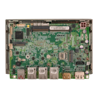
Table of Contents

Other manuals for IEI Technology WAFER-JL-N5105

Questions and Answers:

Question and Answer IconNeed help?

Do you have a question about the IEI Technology WAFER-JL-N5105 and is the answer not in the manual?

IEI Technology WAFER-JL-N5105 Specifications

General IconGeneral
BrandIEI Technology
ModelWAFER-JL-N5105
CategorySingle board computers
LanguageEnglish