EasyManuals Logo

IEI Technology WAFER-JL-N5105 User Manual

IEI Technology WAFER-JL-N5105
79 pages
To Next Page IconTo Next Page
To Previous Page IconTo Previous Page
Page #37 background imageLoading...
Page #37 background image
WAFER-JL-N5105 SBC
Page 25
Pin
Description
1
+3.3V
2
LAN3_LED_LNK#_ACT
Table 3-13: LAN3 LED Connector Pinouts
3.2.9 Battery Connector
CAUTION:
Risk of explosion if battery is replaced by an incorrect type. Only
certified engineers should replace the on-board battery.
Dispose of used batteries according to instructions and local
regulations.
NOTE:
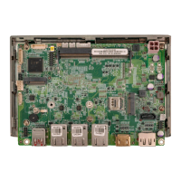
It is recommended to attach the RTC battery onto the system chassis in
which the WAFER-JL-N5105 is installed.
CN Label:
BAT2
CN Type:
2-pin wafer, p=1.25 mm
CN Location:
See Figure 3-11
CN Pinouts:
See Table 3-14
The battery connector is connected to the system battery. The battery provides power to
the system clock to retain the time when power is turned off.

Table of Contents

Other manuals for IEI Technology WAFER-JL-N5105

Questions and Answers:

Question and Answer IconNeed help?

Do you have a question about the IEI Technology WAFER-JL-N5105 and is the answer not in the manual?

IEI Technology WAFER-JL-N5105 Specifications

General IconGeneral
BrandIEI Technology
ModelWAFER-JL-N5105
CategorySingle board computers
LanguageEnglish