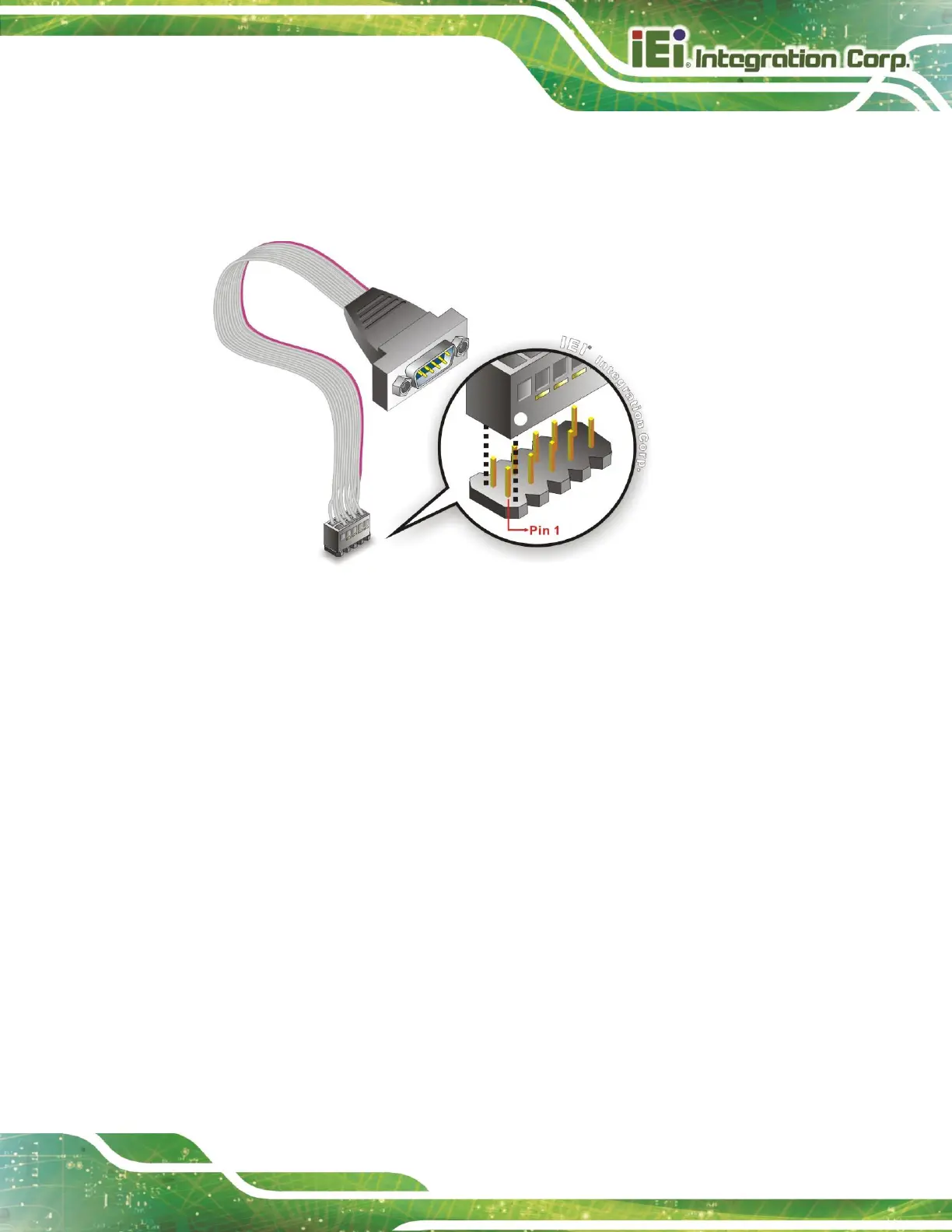
Step 2: Insert the cable connector. Align the cable connector with the onboard
connector. Make sure pin 1 on the board and connector line up. Pin 1 on the
cable connector is indicated with a white dot. See Figure 4-13.
Figure 4-13: Single RS-232 Cable Installation
Step 3: Secure the bracket. The single RS-232 connector has two retention screws
that must be secured to a chassis or bracket.
Step 4: Connect the serial device. Once the single RS-232 connector is connected to
a chassis or bracket, a serial communications device can be connected to the
system.
4.6.4 SATA Drive Connection
The WAFER-JL-N5105 is shipped with a SATA drive cable. To connect the SATA drive to
the connector, please follow the steps below.
Step 1: Locate the SATA connector and the SATA power connector. The locations
of the connectors are shown in Chapter 3.
Step 2: Insert the cable connector. Insert the cable connector into the on-board SATA
drive connector and the SATA power connector. See Figure 4-14.
 Loading...