12
6.3.4 Damping function
With unsteady level (e�g� turbulence, wave movements) display and output
response can be damped� During damping the determined level values are
"smoothed" by means of a mean filter; the result is a steady curve� Damping can
be set by means of the parameter [dAP] (→ 11.4.10)�
[dAP] indicates in seconds after what time 63 % of the final value is reached in the
event of a sudden jump� After 5 x [dAP] almost 100 % has been reached�
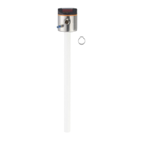
6.3.5 Probes for different tank heights
The unit can be installed in tanks of different sizes� Probes in different lengths are
available� To adapt to the tank height, each probe can be shortened�
The minimum probe length is 150 mm, the maximum probe length 2000 mm�
6.3.6 Defined state in case of a fault
• In case of a fault a safe state can be defined for each output�
• If a fault is detected or if the signal quality is below a minimum value, the
outputs pass into a defined state� Applies to the analogue output according to
Namur recommendation (NE43)� For this case the response of the outputs can
be set via the parameters [FOU1], [FOU2] (→ 11.4.9)�
• The device can pass into the defined error state with delay� This can be useful
if short-term errors occur or the signal is reduced briefly (below the minimum
value), e�g� due to turbulence or foam formation� The delay time can be set
(parameter [dFo] (→ 11.4.11))� During the delay time the last measured value is
frozen� If the measured signal is received again in sufficient strength within the
delay time, the unit continues to work in normal operation� If, however, it is not
received again in sufficient strength within the delay time, the outputs pass into
the defined state�
In case of heavy foam build-up and turbulence, note the examples of how
to create a steady area (→ 7.1.1).