36
11.4.7 Scale analogue signal
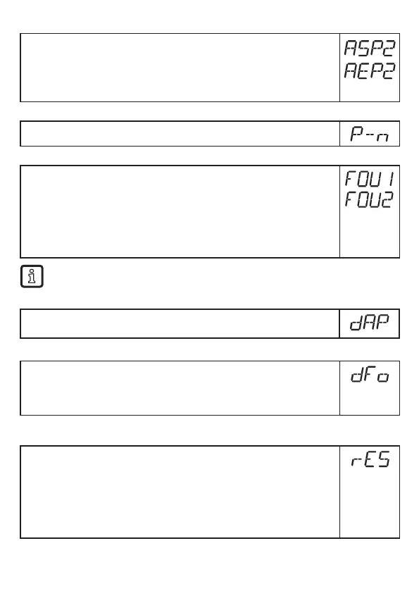
► Select [ASP2] and set the analogue start point�
► Select [AEP2] and set the analogue end point�
Setting these parameters via IO-Link is only possible if parameter [ou2] =
[I] or [InEG]�
More information: (→ 6.3.2)
11.4.8 Set output logic for the switching outputs
► Select [P-n] and set [PnP] or [nPn]�
11.4.9 Response of the outputs in case of a fault
► Select [FOU1] / [FOU2] and set the value:
- [On] = Output switches ON in case of a fault�
Analogue output switches to a value > 21 mA in case of a fault�
- [OFF] = Switching output switches OFF in case of a fault�
Analogue output switches to a value < 3�6 mA in case of a fault�
Examples of faults: defective hardware, signal quality too low�
Overflow is not considered to be a fault�
11.4.10 Set damping for the measured signal
► Select [dAP] and set damping in seconds;
setting range 0,0���60,0 s (→ 6.3.4)�
11.4.11 Set delay time in case of a fault
► Select [dFo] and set a value between 0�0 and 10�0 s�
[dFo] only effective in case of a fault� Mind the dynamics of your application�
In case of fast level changes it is recommended to adapt the value step by
step (→ 6.3.6)�
11.5 Reset all parameters to factory setting
► Select [rES]
► Press [Enter] until [rES] is displayed right aligned
► Press and hold [▲] or [▼] until [----] is displayed.
► Briefly press [Enter]�
> The unit reboots and the factory settings are restored�
Note: On delivery the unit is not operational� First, the basic settings must
be entered (→ 10.2).