8
• When operating with a single probe and small tanks (probe lengths shorter than
200 mm and less than 300 mm distance to the tank wall), interference from the
tank (resonances) may occur in rare cases� Corrective measures: (→ 7.1)
6 Function
6.1 Measuring principle
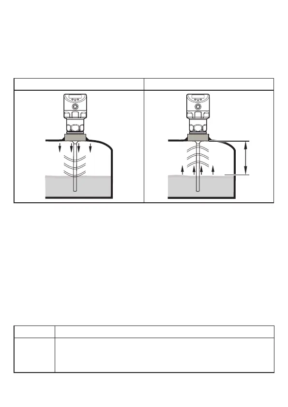
Fig. 6-1 Fig. 6-2
D
The unit operates on the principle of guided wave radar� It measures the level
using electromagnetic pulses in the nanosecond range�
The pulses are transmitted by the sensor head and guided along the probe
(fig� 6-1)� When they hit the medium to be detected they are reflected and guided
back to the sensor (fig� 6-2)� The time between transmitting and receiving the
pulse directly relates to the travelled distance (D) and the current level� The
reference for distance measurement is the lower edge of the process connection�
6.2 Outputs
The unit generates output signals according to the parameter setting� 2 outputs
are available� They can be set separately�
OUT1 Switching signal for level limit value / IO-Link (→ 6.3.7)
OUT2 • analogue signal proportional to the level 4���20 mA / 20���4 mA
or
• switching signal for level limit value