20
For secondary processes:
In case of high mechanical stress (strong vibration, moving viscous media) it
may be necessary to secure the screw connection, e�g� by a screw retaining
compound�
Substances such as screw retaining compounds may migrate into the
medium�
► Make sure that they are harmless�
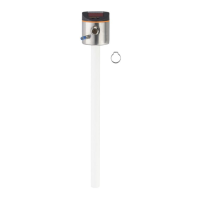
7.3.2 Determine probe length
► Precisely measure the probe length L� The reference point is the lower edge of
the process connection (figure above)�
► Note the value. It is needed for setting the device parameters (→ 11.2.1).
7.4 Installation of the unit in the tank
Before installing and removing the unit: Make sure that no pressure is
applied to the system and that there is no medium in the tank that could
leak� Also always take into account the potential dangers related to extreme
machine and medium temperatures�
The unit can be fixed to different process connections (→ Accessories).
Options are as follows:
1 Fitting by means of a mounting or welding adapter with a sealing ring (hygienic)
► To meet the hygiene regulations use a process adapter with leakage port�
The adapter is supplied with an EPDM O-ring� Further sealing rings (e�g� FKM O-ring)
are available as accessories�
Concerning installation → Installation instructions of the adapter.
2 Installation to G 1 flange / G 1 bush (e.g. for secondary processes)
The sensor is sealed with the sealing ring at the back of the process connection�
The sealing area on the process connection must be flush with the tapped hole and
have a surface characteristic of min� Rz 6�3�
The sensor housing cannot be aligned� With non alignable process
connections (e�g� welding adapters) note the desired position of the sensor
housing (readability of the display, cable entry)� Observe marks at adapters�
If necessary, screw in the unit and mark the required orientation on the
adapter�