35
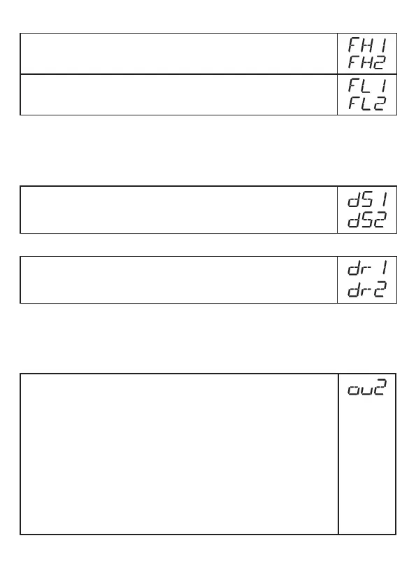
11.4.3 Set the switching limits (window function)
► Make sure that for [oux] the function [Fno] or [Fnc] is set�
► Select [FHx] and set the upper limit of the acceptable range�
► Select [FLx] and set the lower limit of the acceptable range�
[FLx] is always lower than [FHx]� The unit only accepts values which are lower
than the value for [FHx]� If [FHx] is shifted, [FLx] also shifts provided that the lower
end of the setting range is not reached�
11.4.4 Set switch-on delay for switching outputs
► Select [dSx] and set the value between 0�0 and 60 s�
The switch-on delay reacts according to VDMA*)�
11.4.5 Set the switch-off delay for switching outputs
► Select [drx] and set the value between 0�0 and 60 s�
The switch-off delay reacts according to VDMA*)�
*
)
According to VDMA the switch-on delay always has an effect on SP, the switch-
off delay always on rP irrespective of whether the normally open or normally
closed function is used�
11.4.6 Setting of the output function for OUT2
► Select [ou2] and set the switching function:
[I] =
current output 4���20 mA
[InEG] =
current output 20���4 mA
[Hno] =
hysteresis function / normally open
[Hnc] =
hysteresis function / normally closed
[Fno] =
window function / normally open
[Fnc] =
window function / normally closed
Note: If the switching output is used as an overflow prevention, the setting
[ou2] = [Hnc] (normally closed function) is recommended� The
principle of normally closed operation ensures that wire break or cable
break is also detected�