23
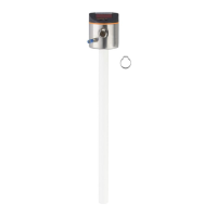
► There must be a hole at least 150 mm in diameter in the plastic lid�
► For installation of the unit, a metal flange plate (= launching plate, R) must be
used which sufficiently covers the drill hole (→ 12.1)
► Ensure a minimum distance (= 80 mm) between the probe and the tank wall�
Adhere to the specified installation instructions according to (→ 7.1.2) to
(→ 7.1.6); if necessary, carry out a tank adjustment�
When installed in plastic tanks, there may be deterioration caused by
electromagnetic interference from other devices� Corrective measures:
• Apply a metal foil to the outside of the tank�
• Apply a shielding screen between the level sensor and other electrical
units
• Additional installation in a metal pipe, permissible diameters: (→ 7.1.2)
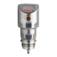
7.4.3 Notes on the use in accordance with EHEDG
The unit is suited for CIP (cleaning in process) when installed correctly�
► Observe the application limits (temperature and material resistance)
according to the data sheet�
► Ensure that the installation of the unit in the system complies with EHEDG
guidelines�
► Use self-draining installation
► Only use process adapters permitted according to EHEDG with special seals
required by the EHEDG position paper�
The gasket of the system interface must not be in contact with the
sealing point of the sensor�
► In case of structures in a tank, the installation must be flush mount� If not
possible then direct water jet cleaning and cleaning of dead spaces must be
possible�
► Install leakage ports so that they are clearly visible�