30
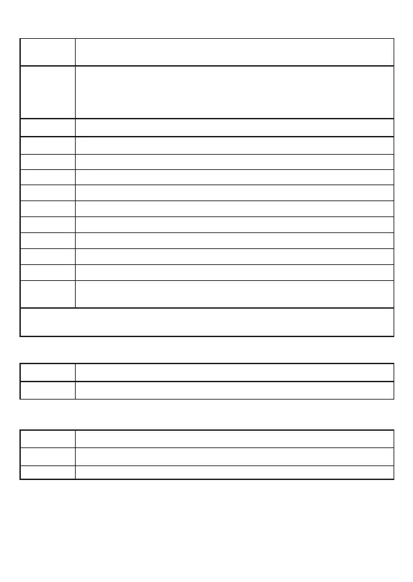
10.2.3 Level CFG (configuration)
ou1
Output configuration for OUT1: switching signal for level limit value�
Hysteresis or window function, normally closed or normally open
ou2
Output configuration for OUT2:
• analogue signal for current level, 4…20 mA or 20…4 mA
• switching signal for level limit value� Hysteresis or window function,
normally closed or normally open
dS1
Switch-on delay for OUT1
dr1
Switch-off delay for OUT1
dS2*
Switch-on delay for OUT2
dr2*
Switch-off delay for OUT2
uni
Selection of the unit of measurement on the sensor display; mm or inch
P-n
Output polarity for the switching outputs; positive or negative switching
FOU1
Response of OUT1 in case of a fault
FOU2
Response of OUT2 in case of a fault
SELd
Selection of the type of indication
dAP
Damping of the measured signal (mean filter)
dFo
Delay time for the outputs to pass into the state defined with FOUx; only
effective in case of a fault�
* Menu item only visible if hysteresis or window function is selected
([ou2] = [H��] or [°F��])�
10.2.4 Level ENV (environment)
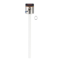
LEnG Input of the probe length
MEdI Medium selection
10.2.5 SIM level (simulation)
S�LvL Simulation of a level / an error state
S�Tim Simulation duration 1���60 min
S�On Simulation start/stop