39
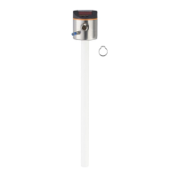
12.2 Operation with a bypass or still pipe (non hygienic)
In certain applications it is recommended to use a bypass or still pipe, e�g� in case
of heavy foam build-up (→ 7.1.6)�
Minimum internal pipe diameter: (→ 7.1.2)
General installation instructions: (→ 7.1)
12.3 Function check
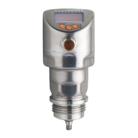
After power-on the device is in the operating mode� It carries out its measurement
and evaluation functions and generates output signals according to the set
parameters�
► Check whether the unit operates correctly�
12.4 Operating indicators
---- continuous Initialisation phase after power on
On delivery the unit is not operational� Basic settings required
(→ 11.2)�
[----] Level below the active zone
Numerical value + LED 1 Current level in mm
Numerical value + LED 2 Current level in inches
Numerical value + LED 3 Current level in % of the scaled measuring range
LED 7 / LED 8 Switching status OUT2 / OUT1
[FULL] + numerical value
alternately
Level has reached or exceeded the maximum measuring
range (= overflow warning)�
[SIM] + xxx Simulation active� XXX = state to be simulated (→ 11.7)
[S�On] Simulation stopped(→ 11.7)
[Loc] Unit locked via operating keys; parameter setting impossible�
For unlocking press the two setting buttons for 10 s�
[uLoc] Unit is unlocked / parameter setting is possible again�
[C�Loc] The unit is temporarily locked� Parameter setting via IO-Link
active
[S�Loc] Unit permanently locked via IO-Link� Unlocking is only
possible via IO-Link�