45
16 Notes on parameter setting via IO-Link
On delivery the unit is not operational�
During set-up, valid basic settings have to be sent to the device once even if the
default settings correspond to the connected device� Make sure that the basic
settings are entered correctly according to the attached probe and the medium to
be detected�
16.1 Application example
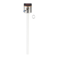
► Enter probe length (parameter [LEnG])� Example:
[LEnG] = [1000] mm�
► Scale analogue output (parameters [ASP2] and [AEP2]; [AEP2] must at least
be 20 % greater than [ASP2]!)� Example:
[AEP2] = [970] mm�
► Alternatively: Set parameter [ou2] to [H��] or [F��])�
► Select the medium (parameter [MEdI])� Example:
[MEdI] = [MId]�
• [HIGH] = For water and water-based media� Operating mode is optimised for
suppression of deposits on the probe�
• [MId] = For water-based media and media with a mean dielectric constant
value� Operating mode is optimised for media with increased foam build-up�
► Transfer the sensor data to the unit�
► Carry out a tank adjustment depending on the installation (parameter [tREF] or
button "TEACH_TANK_REF")�
If the adjustment distance (parameter [RefDist]) is to be adapted, this individual
parameter has to be sent to the sensor first� Then the tank adjustment can
be carried out� Select the adjustment distance according to, for example, the
height of connection pieces or the position of structures in the tank� Within the
adjustment distance, starting from the process connection, interfering reflections
are compensated� Example:
[RefDist] = [50] mm�
► Now all other settings can be carried out�