13
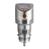
6.3.7 IO-Link
The device has an IO-Link communication interface which requires an IO-Link
capable module (IO-Link master)�
The IO-Link interface enables direct access to the process and diagnostic data
and provides the possibility to set the parameters of the unit during operation�
In addition, communication is possible via a point-to-point connection with a USB
adapter cable�
The IODDs necessary for the configuration of the unit, detailed information about
process data structure, diagnostic information, parameter addresses and the
necessary information about the required IO-Link hardware and software can be
found at www�ifm�com�
6.3.8 Simulation functions
Various levels and errors can be simulated for set-up, maintenance or interference
reduction� The duration of the simulation can be selected (1 min���1 h)� The
simulation can be started manually and runs until it is stopped manually or the
set time elapses� During the simulation the outputs respond according to the
simulated process values (→ 11.7) to (→ 11.7.3)�
7 Installation
7.1 Installation location / environment
► For applications in hygienic areas: (→ 7.4.3) (→ 7.4.4)
• Vertical installation from the top is preferred�
► Observe the notes on tank adjustment (→ 7.1.7)�
• Installation preferably in closed, metal tanks or bypass pipes (→ 7.1.2)�
• For installation in open tanks (→ 7.4.1)
• For installation in plastic tanks (→ 7.4.2)�
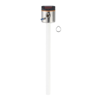
• When operating the unit in small tanks (probe lengths shorter than 200 mm
and less than 300 mm distance to the tank wall), mount the unit off-centre
(eccentrically) to prevent possible interference from tank resonances�