Do you have a question about the Ikegami BS-98 and is the answer not in the manual?
Covers handling precautions for the product, power, environment, and module safety.
Outlines safety procedures for product maintenance and recommended regular maintenance.
Explains manual structure, symbols, notations, illustrations, and related documents for effective reading.
Describes the capabilities and technical features of the BS-98 base station.
Details the technical specifications, including formats, signals, and physical characteristics.
Provides visual representations and measurements of the BS-98 unit.
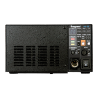
Identifies and explains the controls and indicators on the front panel of the BS-98.
Identifies and explains the connectors and modules on the rear panel of the BS-98.
Explains various HDTV formats supported by the BS-98, including 2-3 pull down and segmented frame.
Describes the input/output connectors and connection examples for synchronizing signals.
Covers essential preparation steps before operating the equipment, including power safety.
Explains how to supply power to the BS and the camera head, including connection methods.
Details the physical connection process between the BS and the camera head using a camera cable.
Illustrates typical system configurations for connecting the BS with cameras and control units.
Describes network configurations like ARCNET connection for system operation.
Details various connectors for external devices like cameras, audio, and communication systems.
Explains how to navigate and use the BS menu for various settings and configurations.
Describes how to configure modules using hard switches for external system compatibility.
Explains the meaning of front panel indicators and the actions to take when they light up.
Details the alarm indicator behavior and how to use self-diagnostic information to identify issues.
| Brand | Ikegami |
|---|---|
| Model | BS-98 |
| Category | Microphone system |
| Language | English |