13
BS-98 1409 VER1 (U) (E)
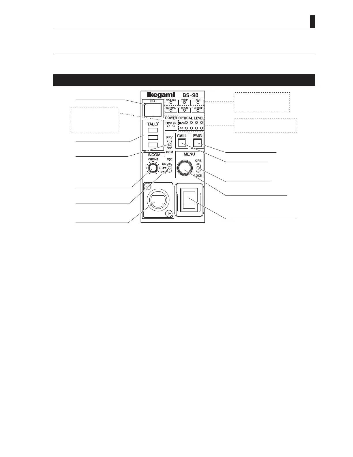
2.1 BS-98 Front View
2.1 BS-98 Front View
This section explains the names and functions of the parts on the front of the BS-98.
BS-98 front display and operation unit
①IDdisplay
②TALLYindicators
③INCOMCOMMON/
PRIVATEswitch
⑤INCOMPHONEknob
④INCOMMICswitch
⑥INCOM
HEADSETconnector
⑪BSMAINPOWER
indicator
⑫HEADPOWER
indicator
⑦GENLOCKindicator
⑧TEMPindicator
⑨FANindicator
⑩CABLE&OPTICALLEVEL
indicators
⑬EMG/PMswitch
⑭CALLswitch
⑮MENUswitch
⑯MENUcontrolswitch
⑰BSMAINPOWERswitch
①
ID display
ARCNET ID or the camera program number is displayed.
It can be set with "FUNCTION SETTING" item on ENGINEER (2/2) page of the BS menu.
- For ARCNET ID, a set value of 1 to 255 (decimal number ) is displayed in a hexadecimal number.
- For CAM PGM No., a set value of 1 to 99 is displayed.
②
TALLY indicators
Indicators for Red TALLY, Green TALLY and Yellow TALLY.
R TALLY : Lights when the R TALLY signal is input to the TALLY IN connector on the rear of the BS. It also lights while the
CALL switch on the camera head or on any control panel (such as OCP, MCP, and RCP) is pressed.
G TALLY : Lights when the G TALLY signal is input to the TALLY IN connector on the rear of the BS.
Y TALLY : Lights when the Y TALLY signal is input to the TALLY IN connector on the rear of the BS.
③
INCOM COMMON/PRIVATE switch
Selects the intercom conversation mode.
COMM : Conversation among the camera head, BS, and system is enabled.
PRV : Conversation between the camera head and BS is enabled.
④
INCOM MIC switch
Selects ON/OFF/PTT for the intercom headset microphone.
ON : Turns ON the intercom microphone.
OFF : Turns OFF the intercom microphone.
PTT : Turns ON the intercom microphone while this switch is pressed down. (Press To Talk)
⑤
INCOM PHONE knob
Controls the volume of the intercom receiver.
⑥
INCOM HEADSET connector
Connects the intercom headset. The connector type varies according to the regional and specifications.
 Loading...