19
BS-98 1409 VER1 (U) (E)
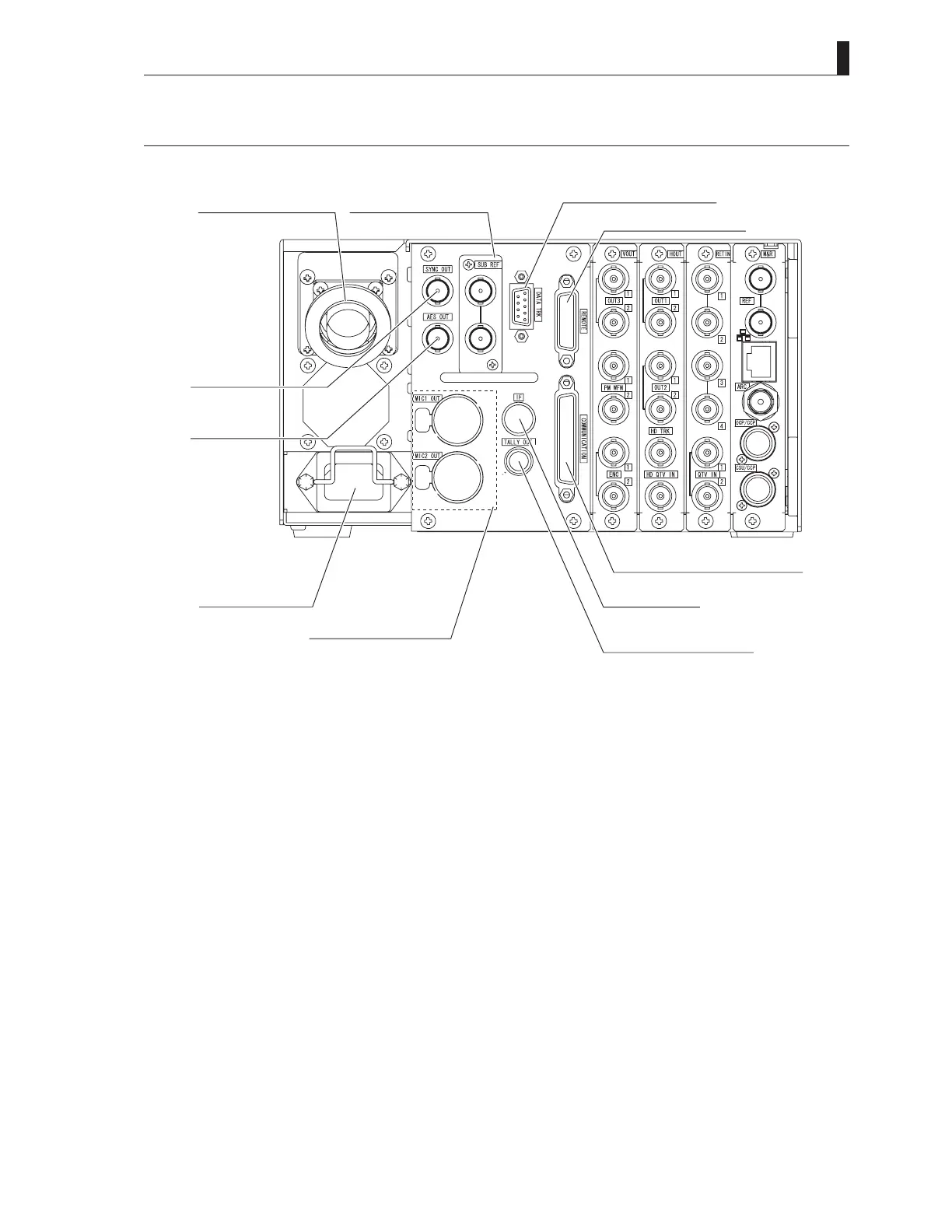
2.2 BS-98 Rear View
2.2 BS-98 Rear View
This section explains the names and functions of the parts on the rear of the BS-98.
①CAMERAconnector
⑥SYNCOUT
connector
⑦AESOUT
connector
⑩ACPowerinlet
⑪SUBREFconnector
③DATATRKconnector
④REMOTEconnector
②MICOUTconnector
⑤COMMUNICATIONconnector
⑨IFconnector
⑧TALLYOUTconnector
Reference:
For model names of connectors and details of assignments, refer to "4.6 Connector for External Connection".
①
CAMERA connector
Optical fiber composite camera cable, This connector is to connect the camera head and the BS.
②
MIC OUT connectors
Output the audio signals that are input to the MIC IN connectors on the camera head. (2 channels analog audio)
③
DATA TRK connector
This is a connector for RS-422 communication with the camera head. (Channel #1)
④
REMOTE connector
This is a connector used to externally control the microphone gain of the camera head.
⑤
COMMUNICATION connector
This connector is used for a connection with an external system.
Input/output of Intercom system, program audio input, and TALLY control input are assigned.
⑥
SYNC OUT connector
The signal for synchronization of the external equipment is output. In "SYNC OUT" setting under "ENGINEER (1/2)" ->
"OUTPUT FORMAT" in BS menu, HDTV Tri-Level sync signal output or SDTV synchronizing signal output can be selected.
Note) SDTV synchronizing signal is not the BBS.
⑦
AES OUT connector
It is an output connector of the digital audio signal (75Ω output). The signal is conformable to the AES/EBU format.