20
BS-98 1409 VER1 (U) (E)
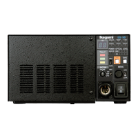
2.2 BS-98 Rear View
⑧
TALLY OUT connector
TALLY OUT signals that are used for external control device.
⑨
IF connector
DATA TRUNK #2, Camera head power ON/OFF indicator output, PREVIEW output, and other functions are assigned.
(In order to use the Channel # 2, the camera head side is also need to be addressed)
⑩
AC power inlet
This inlet is used to connect the AC cable to the BS and to operate the AC power supply.
* The input voltage ranges are 100 to 120 VAC +/- 10% and 220 to 240 VAC +/- 10%.
⑪
SUB REF connector (SUB Rreference)
When the output format is 1080P/23.98PD (2-3 pull-down), 1080P/23.98, and 1080P/23.98sF (segment frame), the 23.98P signal
and the 2-3 pull-down signal phases can be adjusted by inputting the following signals.
●
When setting one unit of BS-98 as a master and synchronization other 2-3 pull-down signals of
BS-98 or CCU-980 phases
Input the HDTV Tri-level sync signal with 10 FIELD ID, which is output from the SYNC OUT connector of the master BS-98,
to the SUB REF connector of other BS/CCU.
●
When synchronization 23.98P signal and 2-3 pull-down signal to the phase of reference signal
Input the synchronizing signal of the 23.98P format. However, when inputting the synchronizing signal in 59.94I format to the
BS/CCU REF connector, phases of the synchronizing signals in the 23.98/P format and in the 59.94I format must match to each
other.)
Reference:
Refer to "3.2 GENLOCK System" for details.