14
BS-98 1409 VER1 (U) (E)
2.1 BS-98 Front View
⑦
GENLOCK indicator (green)
The indicator lights on when the proper synchronous coupling occurred to an external synchronizing signal that was input to BS.
⑧
TEMP indicator (red)
CAUTION:
Lights when the internal temperature of the BS increases abnormally.
When this indicator lights on, check that the ventilation hole on the front panel and the exhaust hole on the rear panel are not
covered or clogged with dust.
⑨
FAN ALARM indicator (red)
CAUTION:
The indicator lights on when the cooling fan inside of the BS POWER stops.
When the alarm is lit, immediately stop operating the equipment and turn off the power supply.
⑩
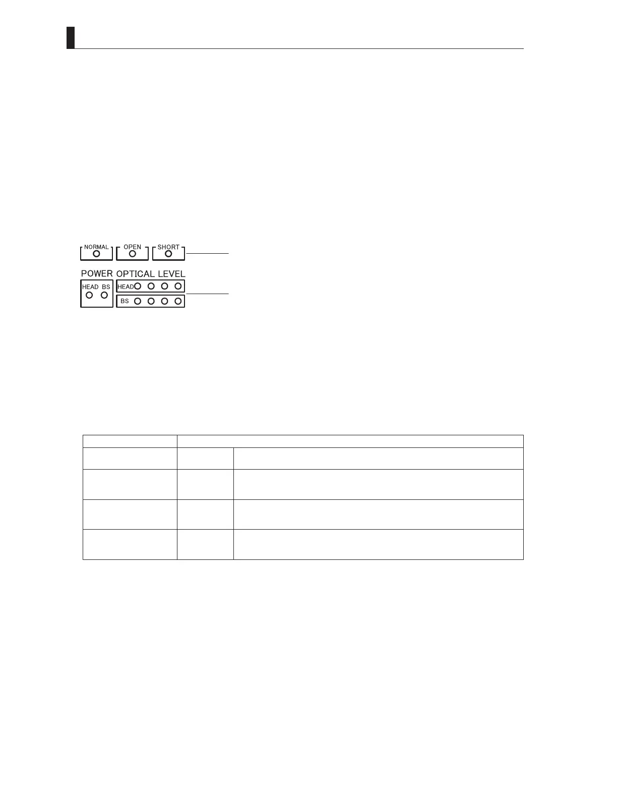
CABLE & OPTICAL LEVEL indicators
· CABLE indicators
The indicator that displays the status of the Hybrid Fiber-Optic Camera Cable status.
NORMAL (green) : It lights up when the Hybrid Fiber-Optic Camera Cable is normal.
OPEN (red) : It lights up when the Hybrid Fiber-Optic Camera Cable is not connected or is broken.
SHORT (red) : It lights up when the power supply line of the Hybrid Fiber-Optic Camera Cable is short-circuited or
when the power contact pins are short-circuited by water drop, etc. The camera will not power up when
this indicator lights.
· OPTICAL LEVEL indicators
This is a light receiving indicator of the optical level. "HEAD" indicates the receiving condition at the camera head side, and
"BS" indicates the light receiving condition at the BS side.
Lighting Status Light Reception Status
R Yl Gr Gr
●○○○
OK Light reception status is good.
R Yl Gr Gr
●○○●
ATTENTION The light reception level is low.
Although there is no problem with the reception of signals transmitted, cleaning the fiber
connector is may be required, unless attenuation is due to very long cable length.
R Yl Gr Gr
●○●●
WARNING The light reception level is very low.
There might be a problem with the reception of signals transmitted. Immediate cleaning
the fiber connector is recommended.
R Yl Gr Gr
○●●●
NG The light cannot be received.
There is a problem with the reception of signals transmitted. Cleaning the fiber connector
is required; or replace the cable since the camera cable might be broken.
(
○
: ON/
●
: OFF)
⑪
BS MAIN POWER indicator (green)
Lights when the BS main power is ON.
⑫
HEAD POWER indicator (orange)
Lights when power is supplied from the BS to the camera head.
⑬
EMG/PAGE switch
Two functions are assigned depending on the BS state.
-PAGE function
When the BS power supply is on and is in the operating condition.
It works as a changeover switch for various information pages displayed for the output of the picture
monitor.
-EMG function
When the BS power supply is off (EMERGENCY function)
When the BS main power supply is turned on while the EMG switch is kept pressed, the SYSTEM
FORMAT of BS is forcibly switched to the general-purpose 1080I59.94 and 1080I50 and started up.
CABLEindicators
OPTICALLEVELindicators
 Loading...