43
BS-98 1409 VER1 (U) (E)
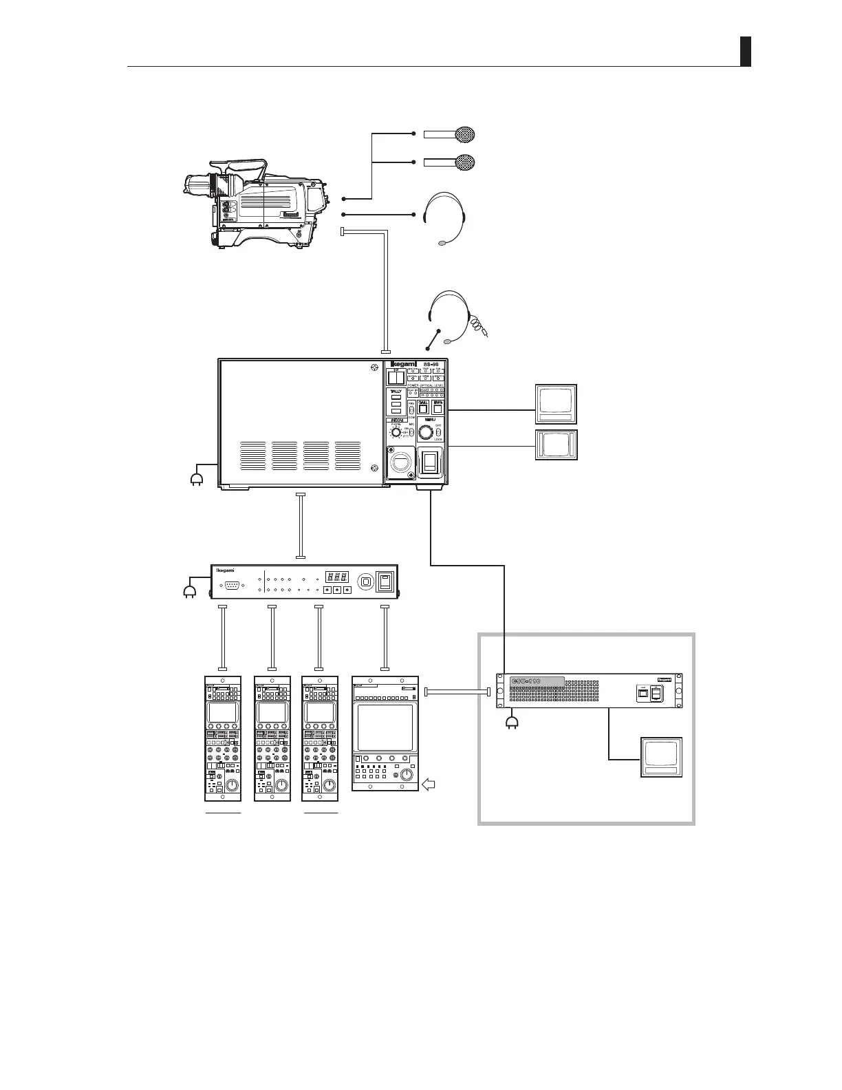
4.4 System Setup Diagram
■
Network Operation
CPH-200
OCP-200 OCP-200 OCP-200
PM
PM
WFM
3G/HD-SDI
SD-SDI(option)
3G/HD-SDI
SD-SDI(option)
PM(SDI)
PM(SDI)
CSU-110
withSDISELECTmodule(optional)
BS-98
CPH-200
CameraCable
Max.1000m
MIC-1
MIC-2
Headset
(ENG/PROD)
Headset
(ENG/PROD)
HDK-97A(FA-97)
*HDK-97A(FA-97)isusedas
anexampleofthecamerafor
explanation.
OCP-200
MCP-200
Coaxialcable
(Networkcommand)
CPCable
(Networkcommand)
MCP
Cable
DCIN
+12V
※1
※2
※2
※3
*1 Network ID of the BS set from the BS menu.
*2 For the maximum and minimum extension length of the cables, refer to "BSH-200/CPH-200 Setup Manual".
*3 For network operation, commands can be selected from an OCP, MCP, or CPH. For video signals, the operating configuration to
select the signals from the CSU-110 is also accepted.
However, an external power supply (DC +12V) is required when the MCP-200 is used and the extension length of the cables is
long.