Home
Image Access
Scanner
WideTEK 25
Page 23 (A.10.1 Connectors on the Back)
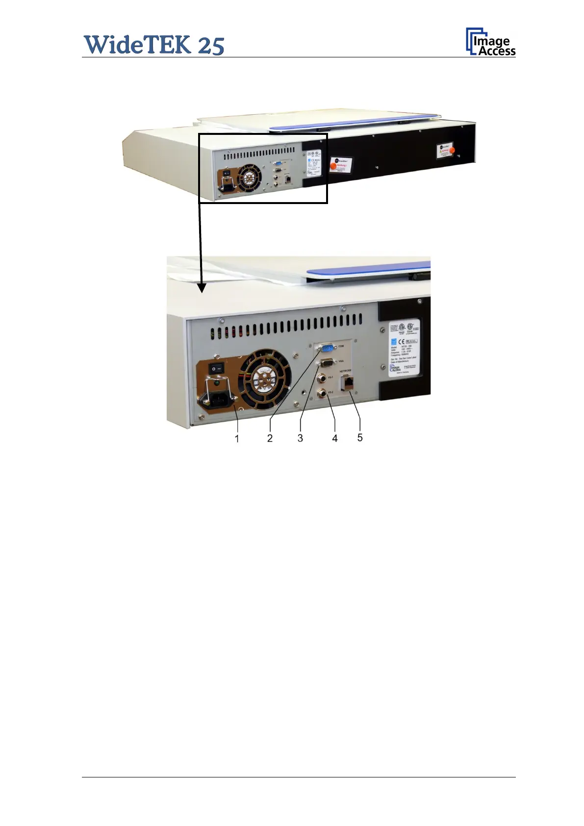
Image Access WideTEK 25 - A.10.1 Connectors on the Back; Picture 6: Back of Widetek 25; Picture 7: Connectors on the Widetek 25
108 pages
Manual
Save Page as PDF
To Next Page
To Next Page
To Previous Page
To Previous Page
Loading...
Manual
Page 23
A
.10.
1
Connector
s on the Bac
k
Picture
6
: Back of WideTEK 25
Picture
7
: Connectors
on the
WideT
EK 25
1:
Pow
er connector and main pow
er switch
2:
Serial connector
3:
VGA connec
tor
4:
Two f
oot pedal connectors
5:
Netw
ork cable conn
ector
22
24
Table of Contents
Main Page
Default Chapter
1
Operation Manual
1
Introduction
4
About this Manual
5
Version History
6
Table of Contents
7
A Hardware
15
Safety Notes
15
Marking of Safety Notes
15
Certification
15
General Notice
15
Safety Precautions
16
A.4 Safety Precautions
16
Device Location
17
Picture 1: Minimum Distances
17
A.5 Device Location
17
Maintenance
18
Touchscreen
18
Surfaces
18
Glass Plate
18
Repair
18
A.6 Maintenance
18
Content on Delivery
19
Picture 2: Scanner Widetek 25 in Transport Box
19
A.8 Content on Delivery
19
Transportation Locks
20
Removing the Transportation Locks
20
Picture 3: Position of Transportation Locks
20
Picture 4: Removing the Transportation Lock
20
A.9 Transportation Locks
20
Inserting the Transportation Locks
21
Picture 5: Inserting the Transportation Lock
21
Connecting to the Power Source
22
A.10.1 Connectors on the Back
23
Picture 6: Back of Widetek 25
23
Picture 7: Connectors on the Widetek 25
23
Powering up the Widetek 25
24
Picture 8: Start Menu Screen
24
Picture 9: Touch Panel While Shut down in Progress
25
A.12.2 Turning-Off the Widetek 25 by the Touch Panel
25
Picture 10: Keyboard with Capital Letters
26
Picture 11: Keyboard with Lower Case Letters
26
A.12.4 Navigating through the Screens
26
Picture 12: Self Test 1
27
Picture 13: Self Test 2
27
A.12.6 Self Test Mode
27
Picture 14: Network Setup
28
Picture 15: Numeric Key Pad
28
Picture 16: Confirm Changes
28
A.12.6.1 IP Address
28
Picture 17: Place the Control Sheet
29
Picture 18: Results of White Balance Test
29
A.12.6.2 White Balance
29
Picture 19: Testing the Touch Panel
30
A.12.6.5 Touch Adjust
30
Picture 20: Stitch Test Screen
31
A.12.6.7 Stitch Test
31
Picture 21: Start Menu Screen
32
A.12.7 Start Menu Screen
32
Picture 22: Output Control 1
33
Picture 23: Viewer Control
33
A.12.8 Output Control Screens
33
Picture 24: E-Mail Address Parameters
34
A.12.8.1.2 Email Address
34
Picture 25: Ftp Server 1
35
Picture 26: Ftp Server 2
35
A.12.8.1.3 FTP Server
35
Picture 27: Network Parameters
36
Picture 28: Input a Network Address
36
A.12.8.1.4 Windows Network
36
Picture 29: Output Control 2
37
Picture 30: System Events and Sound Files
37
A.12.8.2 Output Control 2
37
A.12.9 Image Control Screen
38
A.12.9.1.4 Sharpness
39
A.12.9.2 Image Control 2
40
A.12.9.3 Image Control 3
41
A.12.10 Format Control Screen
42
A.12.10.2 Format Control 2
43
A.12.11 File Control Screen
44
A.12.11.2 Tiff
45
A.12.11.4 Pdf
46
A.12.12 Transport Control Screen
47
A.12.13 Job
48
Picture 40: Creating a Job
49
A.12.13.2 Selecting a Job
50
A.12.14 Software Option: Scan2Vga
51
B Software
52
B.2 the Main Screen
53
Picture 46: Shutdown Confirmation
54
B.2.1 the Options Screen
55
B.2.2 the Properties Screen
57
Picture 50: User Defined Format
59
Picture 51: Additional Margin/Auto Density Slider
60
B.2.3 the Camera Screen
61
B.2.3.1 Threshold Dynamic / Threshold Fixed
63
B.2.4 the Settings Screen
64
Picture 59: Scan Status Window
65
B.2.5 the Format Screen
66
Picture 61: Rectangle Dragged with Mouse
67
B.3 Output Options
68
B.3.1 Output Option Save
69
B.3.2 Output Option Show
70
B.3.3 Output Option Multi
71
Picture 70: Pop-Up Window to Select Images for the "Container
72
B.3.4 Output Option Print
73
B.3.5 Output Option Copy
74
B.3.5.2 Printing Enhancement
77
B.3.6 Output Option FTP Upload
78
B.3.7 Output Option Mail
80
B.3.7.2 Transaction Mode Interactive
82
B.3.8 Output Option Network
83
B.3.8.1 SMB Configuration
84
B.3.9 Output Option Web
85
B.3.9.1 Web Service Configuration
86
B.3.10 Output Option USB
87
B.3.10.1 USB Storage Device
88
B.4 Information
89
B.5 the Setup Screen
90
B.5.2 Access Level User
91
B.5.2.1 Device Info Screen
92
B.5.2.2 Operation Info Screen
93
B.5.2.3 User Settings Screen
94
B.5.2.3.1 Language Selector
95
B.5.2.3.2 Power Saving
96
B.5.2.3.3 Volume
97
B.5.2.3.4 Foot Pedal
98
B.5.2.3.5 Splitting Start
99
C Tests and Troubleshooting
100
C.2 Error Codes
101
C.3 Warnings
103
D Technical Data
104
D.3 Electrical Specifications
105
D.5 CE Declaration of Conformity
106
D.6 FCC Declaration of Conformity
107
Other manuals for Image Access WideTEK 25
Setup And Assembly Manual
70 pages
Related product manuals
Image Access WideTEK 25-600
125 pages
Image Access widetek 44
76 pages
Image Access WideTEK 36
124 pages
Image Access WideTEK 36CL
94 pages
Image Access WideTEK 48CL
72 pages
Image Access WideTEK 48CL-600
94 pages
Image Access Bookeye 5 V2
44 pages
Image Access Bookeye 5 V3
44 pages
Image Access Bookeye 4
122 pages
Image Access bookeye 3
72 pages