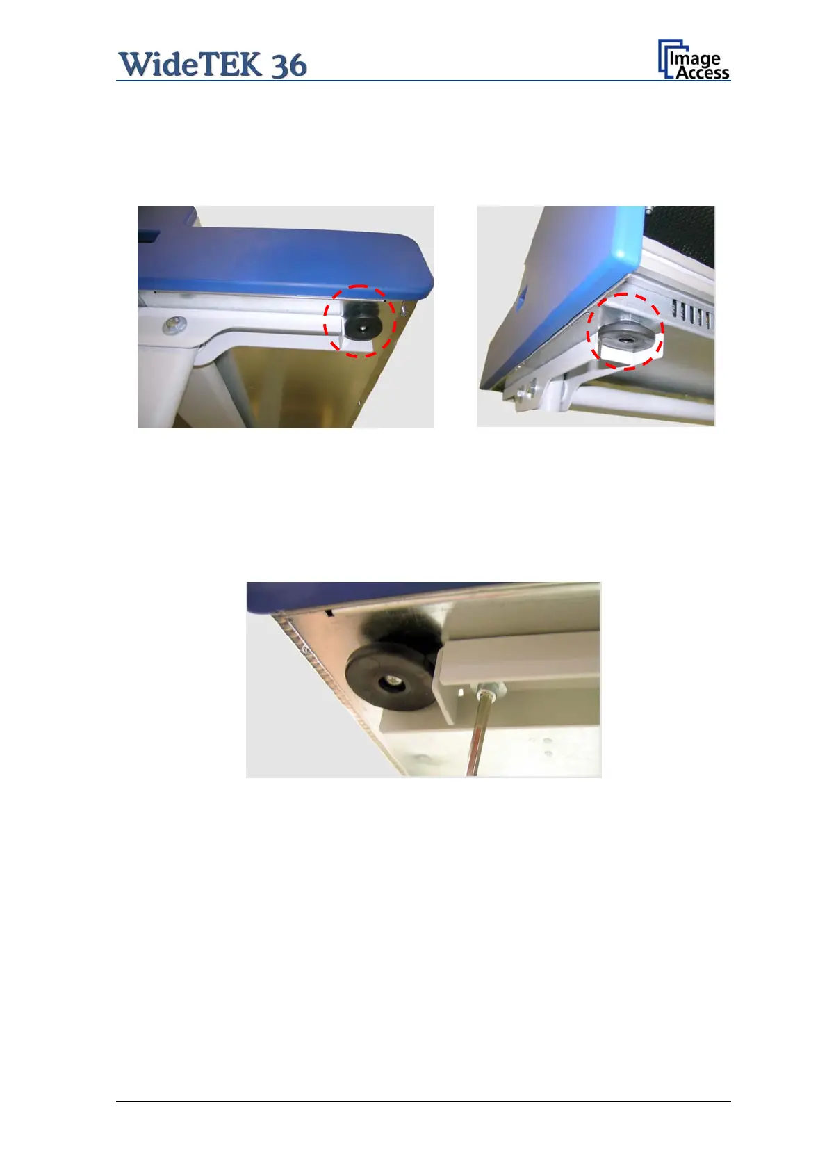
The WideTEK 36 scanner has four pre-mounted rubber feet on its bottom side. The
position of the rubber feet corresponds to the cut-outs at the top of the longitudinal girders.
Place the WideTEK 36 on the floor stand so that the rubber feet are inserted into the cut-
outs.
Picture 16: Bottom side, front side left Picture 17: Bottom side, back side left
Finally, fasten the WideTEK 36 onto the floor stand. The four screws DIN 912 M5x10 with
washers are used to fix the scanner.
Picture 18: Fastening the scanner onto the floor stand
The floor stand has boreholes on each side directly beside the cut-outs for the rubber feet.
Insert the screws and fasten them securely.
Use the Allen wrench to fasten the screws.
Setup and Assembly Manual Page 23

 Loading...