A20733 B0 111
Adjustment and replacement procedures
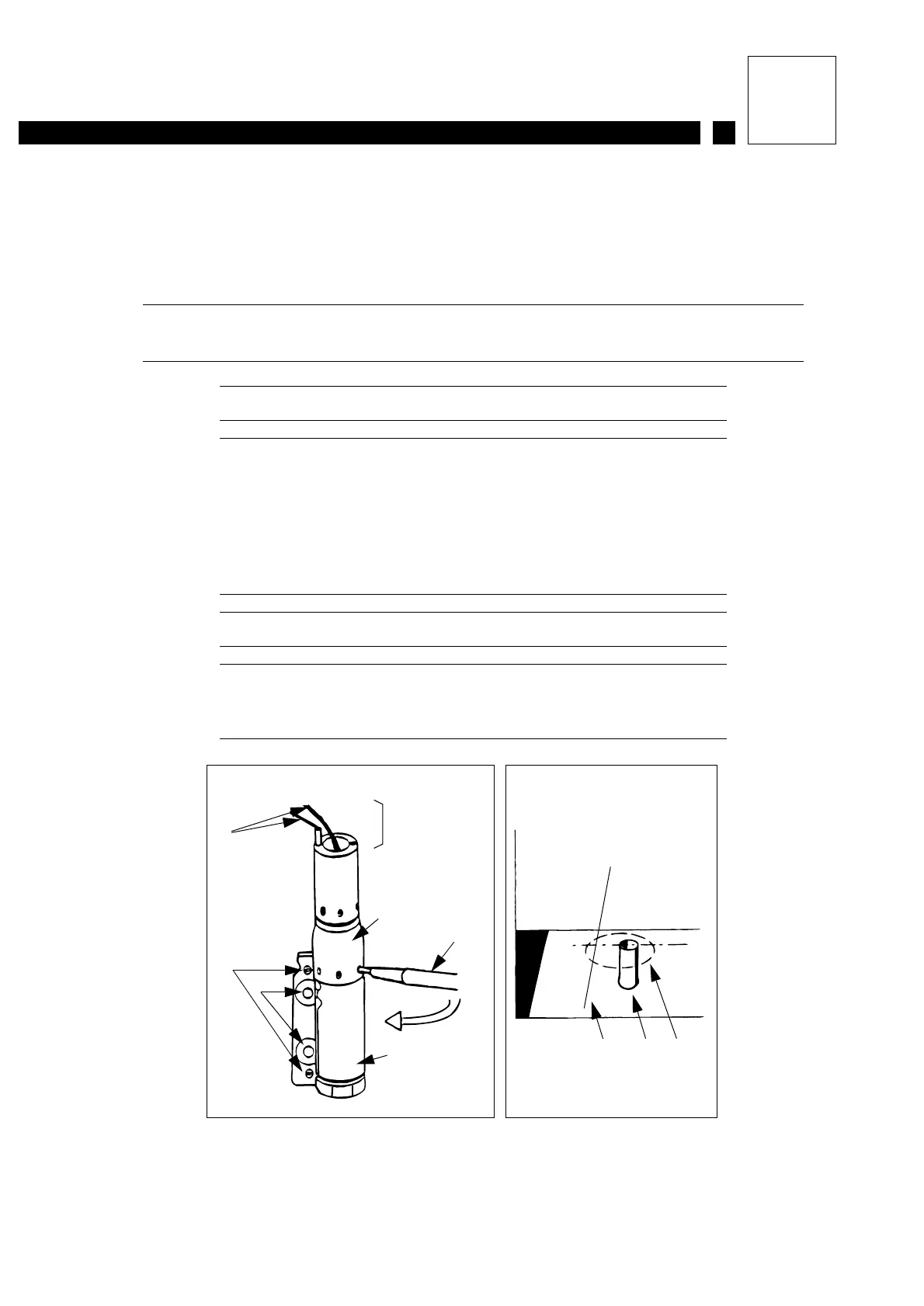
6- Loosen the cannon holder lock screws (see Figure 1).
7- Bring the jet closer to point A or point A’ by pivoting the cannon in the cannon holder using
an orientation tool at the top (Figure 2).
IMPORTANT Rotate in the direction shown on the diagram to avoid
unscrewing the cannon nut.
Figure 1: Canon pressetting
1 Leads to be disconnected
2 Cams
3 Lock screw
4 Orientation tool
5 Cannon holder
6 Protective cover location
7 Cannon
Figure 2: Pressetting the jet in the gutter
1 Jet
2 Gutter
3 Jet trajectory as cannon is rotated
6
7
4
55
2
3
1
32
AA’
Figure 1 Figure 2
1