trapulsPac - User Guide
Chapter 3 – Reference
Software Position Range Limit
The Software Position Range Limit defines a Positive Position Limit and a Negative Position Limit, which act as
hardware limit switches.
The Software Position Range Limit is activated when Axis Type (0x3360) is linear.
Index 0x607D
Name Software Position Range Limit
Object Code ARRAY
Object Class all
Number of Elements 2
Value Description
Sub Index 1
Description Negative Position Limit
Data Type Integer32
Access rw
PDO Mapping No
Unit User position unit
Value
Sub Index 2
Description Positive Position Limit
Data Type Integer32
Access rw
PDO Mapping No
Unit User position unit
Value
3.2.3.4 - Homing Mode
When the feedback sensor does not give the absolute position, the homing mode is the right way to set up the
motor to a known position. This position can be detected by using several signals such as positive or negative
limit switch, home switch, index pulse or mechanical limit. The choice of the homing method depends on those
signals and on the direction of the starting movement.
The drive generates the trajectory according to the homing method. This is the reason why the position loop of the
drive is used.
Graphical representation of the trajectories as a function of the input signals:
Index Object Name Type
ttr.
0x607C VAR Home Offset Integer32 rw
0x6098 VAR Homing Method Integer8 rw
0x6099 ARRAY Homing Speeds Unsigned32 rw
0x609A VAR Homing Acceleration Unsigned32 rw
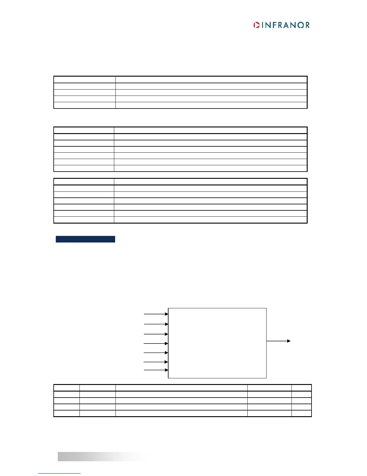
Status word 0x6041
Control word 0x6040
Homing method 0x6098
Homing speeds 0x6099
Homing acceleration 0x609A
Homing offset 0x607C
Homing current limit 0x309C
Homing method
End On Home Position 0x309D
 Loading...

