trapulsPac - User Guide
Chapter 3 – Reference
3.2.5 - APPLICATION FEATURE
3.2.5.1 - Digital Input/Output configuration
Digital Inputs / Outputs
The Xtrapuls drive allows:
- connecting any physical logic input to any bit in any variable,
- connecting any bit in any variable to any physical logic output.
The available logic input functions are:
- Negative Limit Switch
- Positive Limit Switch
- Homing Switch
- Inhibit
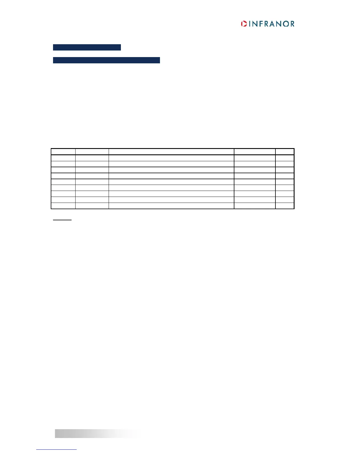
Index Object Name Type Attr.
0x60FD VAR Digital Inputs Unsigned32 ro
0x3050 ARRAY Digital Inputs Configuration Unsigned32 rw
0x3051 VAR Digital Inputs Polarity Unsigned16 rw
0x60FE ARRAY Gem Digital Outputs Unsigned32 rw
0x3054 ARRAY Digital Outputs Configuration Unsigned32 rw
0x3055 VAR Digital Outputs Polarity Unsigned16 rw
0x3058 ARRAY Digital User Inputs/Outputs Unsigned16 rw
0x3059 ARRAY Virtual Inputs/Outputs Unsigned16 rw
0x3043 ARRAY Enable Configuration Unsigned16 rw
Example
: realize an ENABLE input with physical input IN1.
- Drive can move only when 24 V supply is applied,
- When 24 V is lost, drive must stop.
So, IN1 input must be connected to the "Inhibit" function with 0x3050. When the "Inhibit" function is activated with
logic level 1, the input polarity of IN1 must be reversed by object 0x3051.
 Loading...

