17
trapuls – EtherCAT® Fieldbus Interface
Chapter 5 – Synchronization of Xtrapuls EtherCAT® slaves
SYNC TYPE 4: HARD SYNCHRONISATION (STIFF)
The distributed clock is the source of the internal software PLL to synchronize the servo loops. This clock event is
physically the SYNC0 signal generated by the distributed clock of the ESC.
The PDO mapping is performed in the following way:
In this synchronisation type, the EtherCAT® master is also supposed to embed TPDO and RPDO in the same
EtherCAT® telegram.
The EtherCAT® master is responsible for the setup of the SYNC0 cycle time parameter during the communication
start-up phase (PS transition).
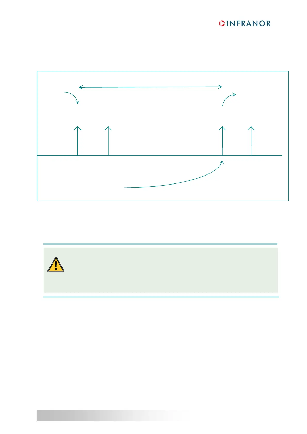
Execution
of RPDOs
Communication cycle period
SM2
Event
(RPDO)
Sampling of
TPDOs
SM2 Event
(RPDO)
Reception
of RPDOs
Transmition
of TPDOs
SYNC0
Event
SM2
Event
(RPDO)
SYNC0
Event
With this type of synchronisation care must be taken during the setup of the master :
Distributed clocks should be enabled by the master.
The SYNC0 cycle time and the cycle task communication period needs to be equal to the
communication cycle period object 1006h.
If one of these conditions is not fulfilled, the transition Preop to Safe-Op will not be performed and the
AL Status Code will be set to 26h, meaning an inconsistent setting.