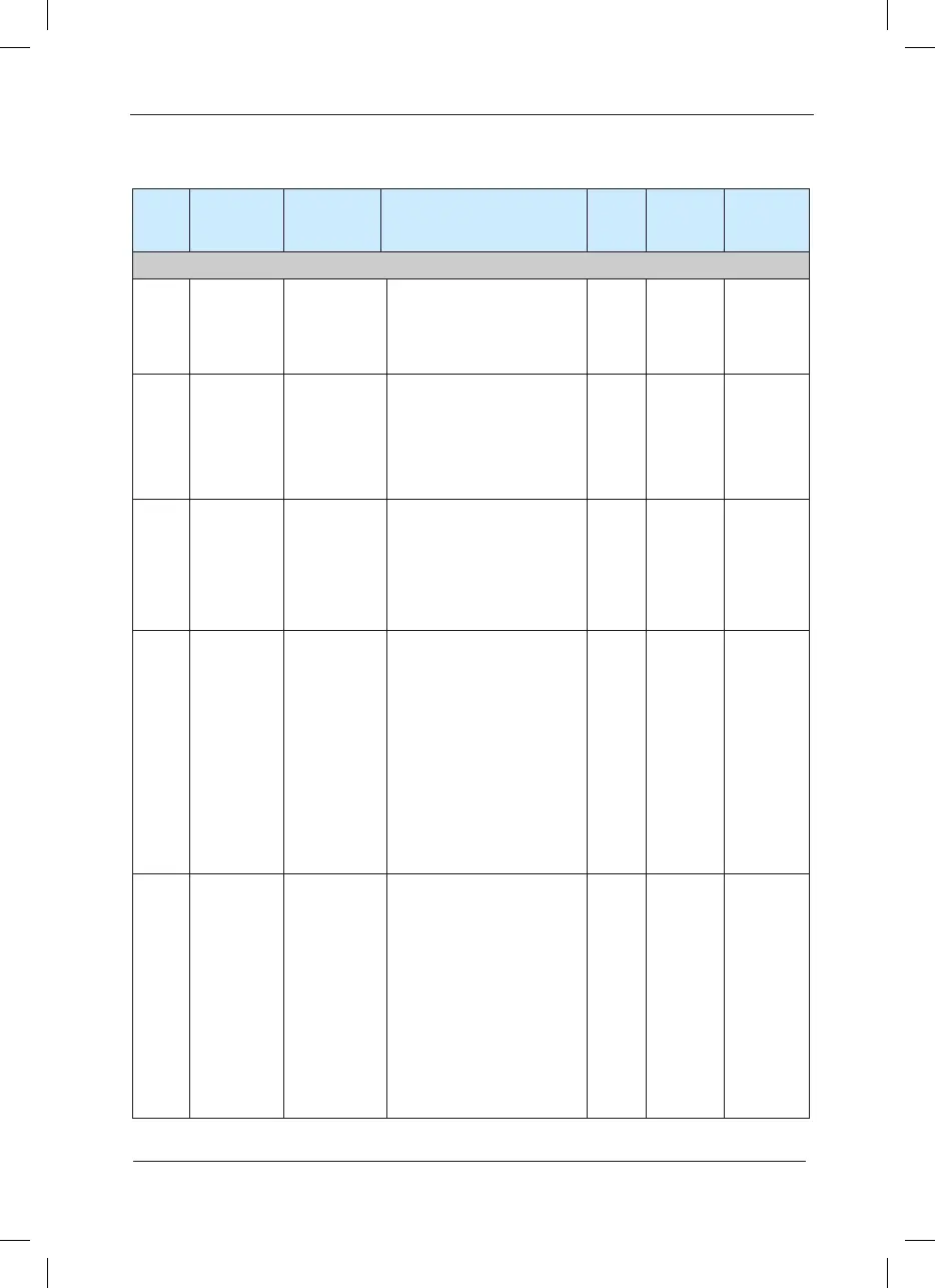
Function Parameter Table
Function
code
Name LED display Set range
Minim-
um unit
Factory
default
value
Modication
description
Group F0 Basic Function Group
F0-00 Model display Model display
1: G model (constant torque load
model)
2: P model (fan and pump load
model)
1
Model
dependent
●
F0-01 Control mode Control mode
0: Speed s e n s o r l e s s vector
control (SVC)
1: Speed sensor vector control
(VC)
V/F control
2:V/F control
1 0
★
F0-02
Command
source
selection
Command
source
selection
0: Oper atio n pane l runn ing
command channel (LED OFF)
1: Terminal command channel
(LED ON)
2: serial port command channel
(LED ashes)
1 0
☆
F0-03
Main
frequency
source X
selection
Main frequency
source X
selection
0: Digital setup UP and DOWN
adjustment (non-recorded)
1: Digital setup UP and DOWN
adjustment (recorded)
2: Al1
3: Al2
4: Al3
5: PULSE setup (Dl5)
6: MS speed
7: PLC
8: PID
9: Communication setup
1 1
★
F0-04
Auxiliary
Frequency
source Y
selection
Auxiliary
Frequency
source Y
selection
0: Digital setup UP and DOWN
adjustment (non-recorded)
1: Digital setup UP and DOWN
adjustment (recorded)
2: AI1
3: AI2
4: AI3
5: PULSE setup (X5)
6: MS speed
7: PLC
8: PID
9: Communication setup
1 0
★
 Loading...
