CUSA
®
Clarity Ultrasonic Surgical Aspirator System Operator’s Manual
3-5
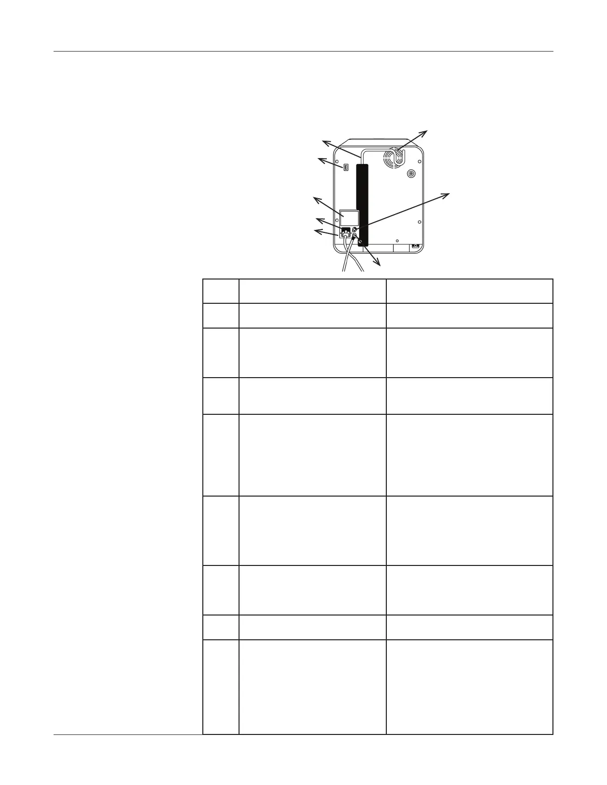
Console – Rear Panel
Console – Rear Panel
The gure illustrates the rear view of the console. The components are
described in the table.
Component Description
➀
System Fan Vent Fan keeps internal system cool.
➁
Potential Equalization
Terminal
For use in locations where
Potential Equalization
Conductors are used.
➂
Footswitch Cable Connector
Connects the footswitch to the
console.
➃
AC Power Cord Connector
Connects the system to the
Mains power supply.
A safety feature prevents the
power cord from being
accidentally unplugged.
➄
Fuses
Protect the system from
electrical overloads.
Refer to “Power Input and
Fusing” on page A-4.
➅
Labels
Displays the console model
number, serial number and
regulatory approvals.
➆
USB Connector Used for service
➇
I.V. Pole
Supports the sterile irrigation
uid container. The pole must be
raised to use it. The pole can be
lowered when not in use.
The safe working load for the
I.V. pole is 2 kg.
➀
➁
➂
➃
➄
➅
➆
➇