27
Installing Antenna
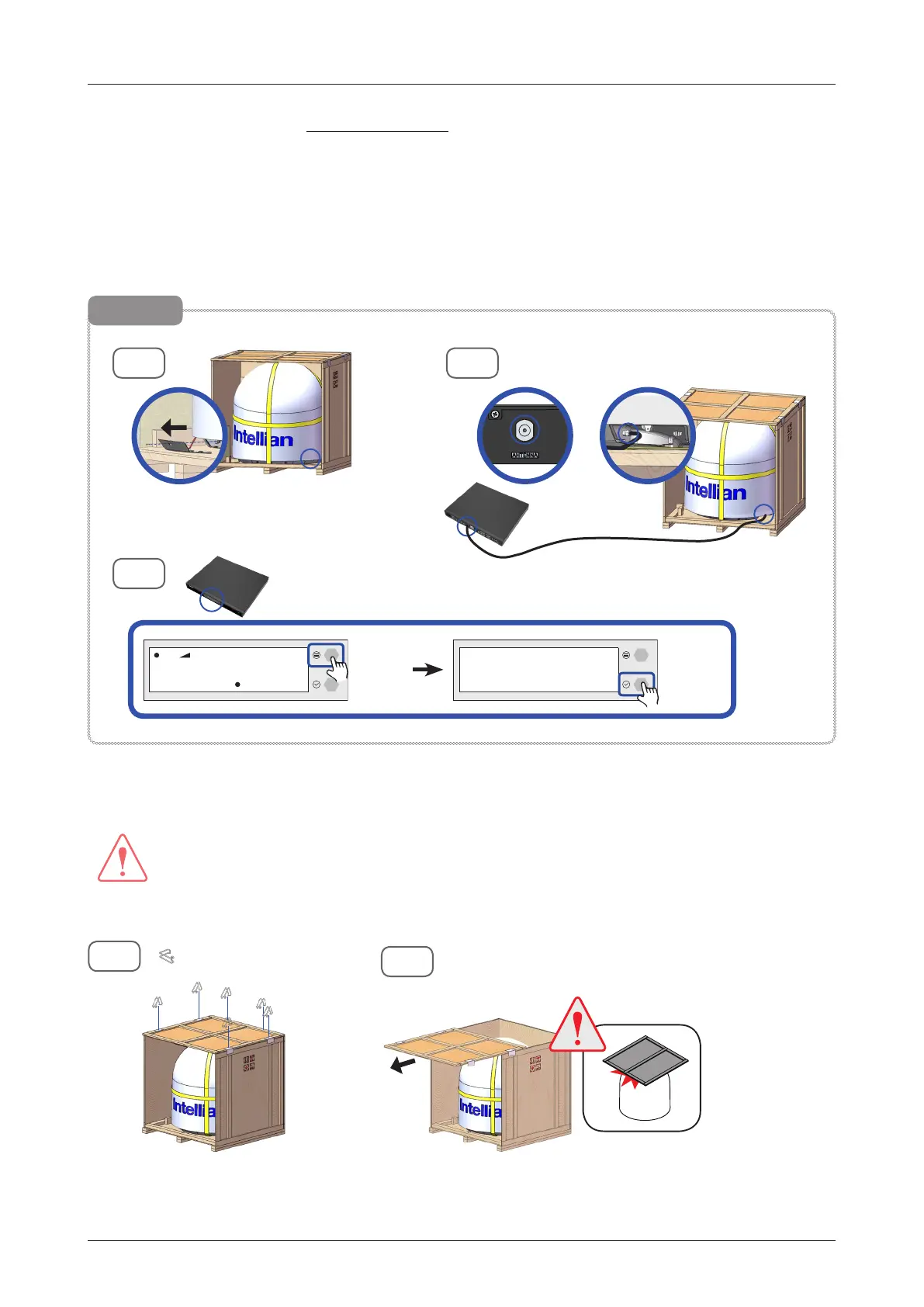
3. Running Diagnostic Tests: This step is optional. After removing one of the side panels, you can run
the diagnostic tests easily to verify the condition of the antenna. First, prepare the "RF Cable (Customer
Supplied)" to connect the antenna and the ACU.
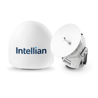
3-1. Remove the M4x15L Wrench Bolt by using the wrench set then open the cable entry cover.
3-2. Connect the "RF Cable
(Customer Supplied)
" from the "ANTENNA" connector on the rear of the ACU to
the "RF Connector" inside cable entry of radome (Antenna).
3-3. Execute diagnostic tests (Full Diagnosis Test) via ACU and check the real-time diagnosis result.
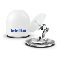
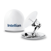
4. Remove the clips (6EA) on the top panel. Detach the top panel by carefully pulling it as shown in the
picture.
WARNING
WARNING
The side brackets at the edge of the top panel secure the side panels and top panel in position. When
pulling the top panel, ensure that the top panel doesn't fall on the radome.
3-1
3-3
DIAGNOSIS
DIAG ALL
Press
Select Key
3-2
Optional
Press
Move Key
SNR F:12.490/11.300 RX:H TX:V
SEARCH 1 062.2 E
HDG:120.4
GPS:
P
RF Cable (Customer Supplied)
Cable Entry Cover
4-1
: 6 EA
4-2
 Loading...