LP600 Users Manual
Rev E, February 2017
Page 27 of 43
Procedure: Calibration (Adjustment)
Tools required:
Calibration force generator; press or deadweights. This calibration source must
cover the range of 10% to 100% of nominal scale capacity with a certified accuracy
of 0.025% of reading or better.
100267 - 10" ( 0.25") x 17" ( 0.25") x 1.75" (minimum) aluminum loading block.
100268-A - 10" ( 0.25") x 17" ( 0.25") x 0.5" ( 0.125") rubber loading scale. (40 to
70 Shore A rating)
140208 - #2 Phillips screwdriver.
140210 - Static dissipation station.
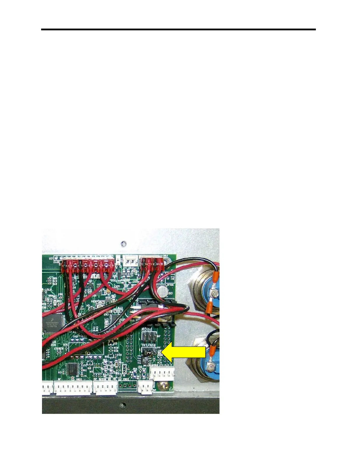
Calibration Enable Jumper
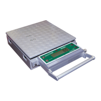
To access the calibration mode the shorting strap labeled “RUN/CAL”, located on the
right-middle of the circuit board (Intercomp, A/D 20 BIT rev E), it must be moved from
shorting pins 2 and 3(RUN); to shorting pins 1 and 2(CAL). To access the shorting
strap, remove the 10 screws on the outside edges of the display assembly. Carefully lift
the display assembly up and place the assembly, display side down, on top of the
weighing platform.
Note: Care must be taken to ensure the wire harness is seated properly to
prevent it from being pinched between the display assembly and the scale
casing.