LP600 Users Manual
Rev E, February 2017
Page 28 of 43
Following calibration, replace the strap to shorting pins 2 and 3 (RUN); replace the
assembly and reattach the assembly with the screws. This will ensure that the
calibration information of the scale is protected from being changed.
Note: Care must be taken to ensure the wire harness is seated properly to
prevent it from pinching between the display assembly and scale casing.
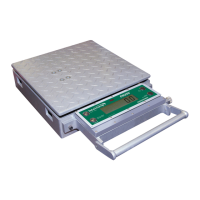
Multiple Corner Adjustment
The corner calibration is set at the factory at time of shipment. It may be necessary to
make adjustments to the corner settings after replacing a load cell or the control printed
circuit board. Corners must be checked if the unit fails the calibration verification check.
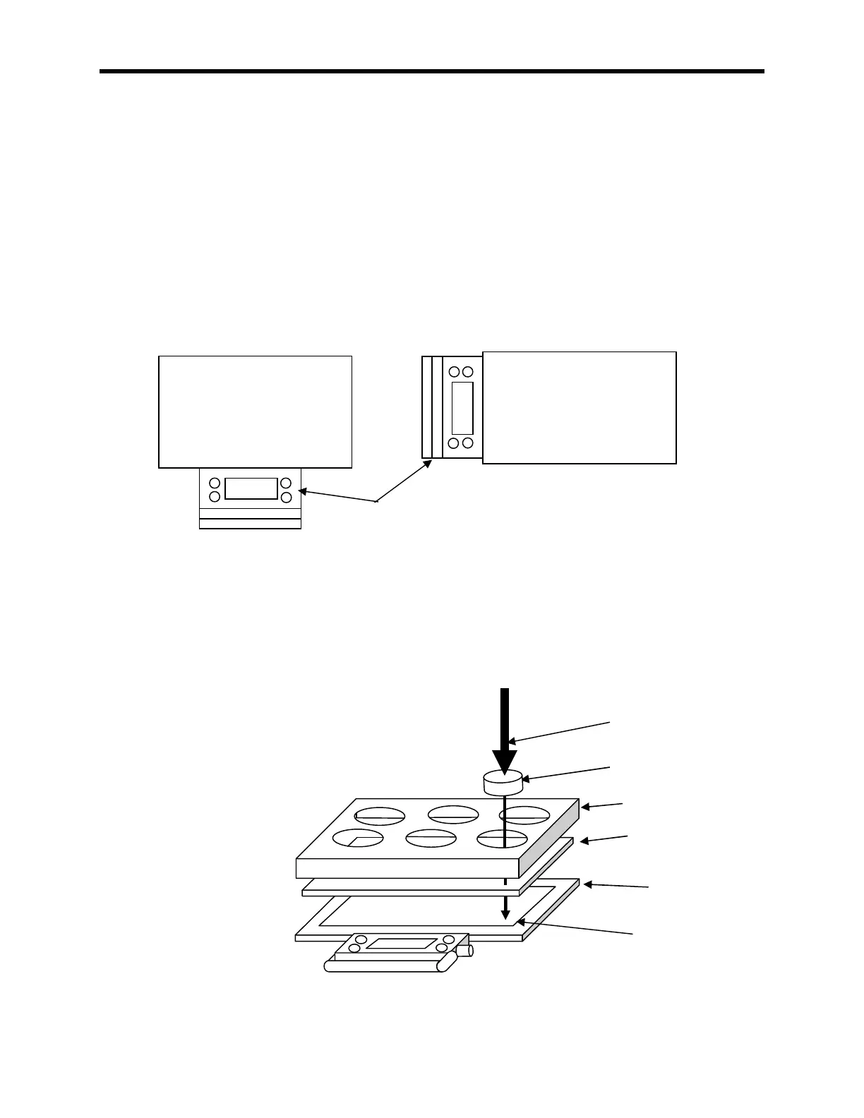
There are six load cells within the LP600 scale; they are numbered as in Figure 1.
Figure 1
Tools required:
3000 pound calibration press.
100259-A - 15" ( 0.25") x 22" ( 0.25") x 0.5" ( 0.125") rubber loading scale. (40 to
70 Shore A rating)
111115 – 3” Calibration Puck
100319 – LP 6 cell corner fixture.
140208 - #2 Phillips screwdriver.
140210 - Static dissipation station.
Figure 2
Assembly and use of corner alignment
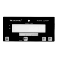
Possible Control Panel positions