EasyManuals Logo

Intermec EasyCoder PC4 Service Manual

Intermec EasyCoder PC4
88 pages
To Next Page IconTo Next Page
To Previous Page IconTo Previous Page
Page #48 background imageLoading...
Page #48 background image
42 Intermec EasyCoder PC4—Service Manual
Chapter 5—Base Frame
Replacement
e base locks come as a kit with two complete assembled units, one for
each side.
Disconnect the cables from JP12 and JP11 on the main board.
Remove the screws that hold the locks.
Install new base locks in reverse order.
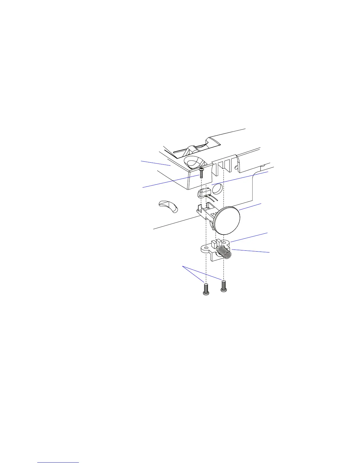
In the illustration below, the right-side base lock is exploded to better show
the principles of design.
Push button
Microswitch
Holder
Spring
Base frame
Screws (2)
Screw

Other manuals for Intermec EasyCoder PC4

Questions and Answers:

Question and Answer IconNeed help?

Do you have a question about the Intermec EasyCoder PC4 and is the answer not in the manual?

Intermec EasyCoder PC4 Specifications

General IconGeneral
Resolution203 dpi
Power Requirements100-240 VAC, 50-60 Hz
Print MethodDirect Thermal
Max Print Width4.09 inches (104 mm)
Max Print Speed4 inches per second
Max Print Length39 inches
Media TypeRoll-fed, die-cut, continuous, fanfold, tags, tickets
Media Width1.0 - 4.65 inches
Media Thickness0.06 mm (0.00236 in) to 0.18 mm (0.00708 in)
InterfaceRS-232
Memory4 MB Flash, 8 MB SDRAM
Operating Temperature5°C to 40°C (41°F to 104°F)
Storage Temperature-4°F to 140°F (-20°C to 60°C)
Humidity10 to 90% non-condensing

Related product manuals