Goodrive35 inverters Product overview
13
Product Overview 3
3.1 What this chapter contains
The chapter briefly describes the operation principle, product characteristics, layout, name
plate and type designation information.
3.2 Basic principles
Goodrive35 series inverters are wall, floor and flange mountable devices for controlling
asynchronous AC induction motors and permanent magnet synchronous motors.
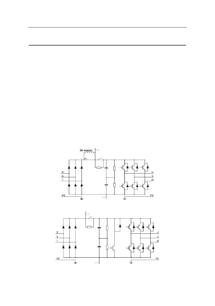
The diagram below shows the simplified main circuit diagram of the inverter. The rectifier
converts three-phase AC voltage to DC voltage. The capacitor bank of the intermediate
circuit stabilizes the DC voltage. The converter transforms the DC voltage back to AC
voltage for the AC motor. The brake pipe connects the external braking resistor to the
intermediate DC circuit to consume the feedback energy when the voltage in the circuit
exceeds its maximum limit.
Fig 3-1 The simplified main circuit diagram (inverters of 380V≥37kW)
Fig 3-2 The simplified main circuit diagram (inverters of 380V≤30kW)

 Loading...


