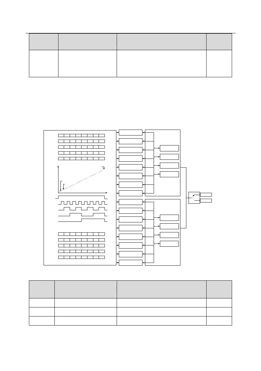
P10.02 multi-stage speed 0
P10.03 the running time of stage 0
P10.04 multi-stage speed 1
P10.05 the running time of stage 1
P10.06 multi-stage speed 2
P10.07 the running time of stage 2
P10.08 multi-stage speed 3
P10.09 the running time of stage 3
P10.10 multi-stage speed 4
P10.11 the running time of stage 4
P10.12 multi-stage speed 5
P10.13 the running time of stage 5
P10.14 multi-stage speed 6
P10.15 the running time of stage 6
P10.16 multi-stage speed 7
P10.17 the running time of stage 7
P10.18 multi-stage speed 8
P10.19 the running time of stage 8
P10.20 multi-stage speed 9
P10.21 the running time of stage 9
P10.22 multi-stage speed 10
P10.23 the running time of stage 10
P10.24 multi-stage speed 11
P10.25 the running time of stage 11
P10.26 multi-stage speed 12
P10.27 the running time of stage 12
P10.28 multi-stage speed 13
P10.29 the running time of stage 13
P10.30 multi-stage speed 14
P10.31 the running time of stage 14
P10.32 multi-stage speed 15
P10.33 the running time of stage 15
BIT0
BIT1
BIT2
BIT3
BIT4
BIT5
BIT6
BIT7
BIT8
BIT9
BIT10
BIT11
BIT12
BIT13
BIT14
BIT15
Terminal function 16
Multi-stage speed 1
Terminal function 17
Multi-stage speed 2
Terminal function 18
Multi-stage speed
terminal 3
Terminal function 19
Multi-stage speed
terminal 1
P10.34
The ACC/DEC time selection of
Stage 0~7 of PLC
P00.10 ACC time 1
P00.12 DEC time 1
P08.00 ACC time 2
P08.01 DEC time 2
P08.02 ACC time 3
P08.03 DEC time 3
P08.04 ACC time 4
P08.15 DEC time 4
00
01
10
11
BIT0
BIT1
BIT2
BIT3
BIT4
BIT5
BIT6
BIT7
BIT8
BIT9
BIT10
BIT11
BIT12
BIT13
BIT14
BIT15
P00.10 ACC time 1
P00.12 DEC time 1
P08.00 ACC time 2
P08.01 DEC time 2
P08.02 ACC time 3
P08.03 DEC time 3
P08.04 ACC time 4
P08.15 DEC time 4
00
01
10
11
The ACC/DEC time selection of
Stage 8~15 of PLC
Multi-stage speed
output
Running command
Multi-stage
speed 0
Multi-stage
speed 1
Multi-stage
speed 15
ON
OFF
OFF ON
Terminal function 16
Multi-stage speed
terminal 1
Terminal function 17
Multi-stage speed
terminal 2
Terminal function 18
Multi-stage speed
terminal 3
Terminal function 19
Multi-stage speed
terminal 4
OFF ON OFF ON OFF ON
OFF ONOFF ON OFFON OFF ON
OFF ONOFF ONOFF ONOFF ON
Multi-stage
speed
8 9 10 11 12 13 14 15
ON ONON ON ON ONON ON
OFF ON
Terminal function 16
Multi-stage speed
terminal 1
Terminal function 17
Multi-stage speed
terminal 21
Terminal function 18
Multi-stage speed
terminal 3
Terminal function 19
Multi-stage speed
terminal 4
OFF ON OFF ON OFF ON
OFF ONOFF ON OFFON OFF ON
OFF ONOFF ONOFF ONOFF ON
OFF OFF OFF OFF OFF OFF OFF OFF
Multi-stage
speed
0 1 2 3 4 5 6 7
Frequency
retention
Valid
Invalid

 Loading...


