Goodrive35 inverters Communication protocol
267
or the device has a special message format. For example, when the upper monitor is
running, if the operator clicks sending command bottom, the upper monitor can send
command message actively even it can not receive the message form other devices. In this
case, the upper monitor is the master. And if the designer makes the inverter send the data
only after receiving the command, then the inverter is the slave.
The master can communicate with any single slave or with all slaves. For the single-visiting
command, the slave should feedback a response message; for the broadcasting message
from the master, the slave does not need to feedback the response message.
10.3 Application of the inverter
The Modbus protocol of the inverter is RTU mode and the physical layer is RS485.
10.3.1 RS485
The interface of RS485 works on semiduplex and its data signal applies differential
transmission which is called balance transmission, too. It uses twisted pairs, one of which is
defined as A (+) and the other is defined as B (-). Generally, if the positive electrical level
between sending drive A and B is among +2~+6V, it is logic“1”, if the electrical level is among
-2V~-6V, it is logic“0”.
485+ on the terminal board corresponds to A and 485- to B.
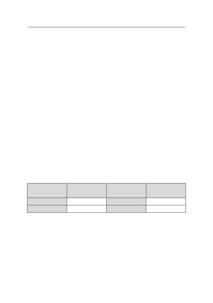
Communication baud rate means the binary bit number in one second. The unit is bit/s (bps).
The higher the baud rate is, the quicker the transmission speed is and the weaker the
anti-interference is. If the twisted pairs of 0.56mm (24AWG)is applied as the communication
cables, the Max. Transmission distance is as below:
Max. transmission
distance
Max. transmission
distance
It is recommended to use shield cables and make the shield layer as the grounding wires
during RS485 remote communication.
In the cases with less devices and shorter distance, it is recommended to use 120Ω terminal
resistor as the performance will be weakened if the distance increase even though the
network can perform well without load resistor.
10.3.2.1 Single application
Figure 1 is the site Modbus connection figure of single inverter and PC. Generally, the
computer does not have RS485 interface, the RS232 or USB interface of the computer

 Loading...


