Goodrive35 inverters Appendix B
308
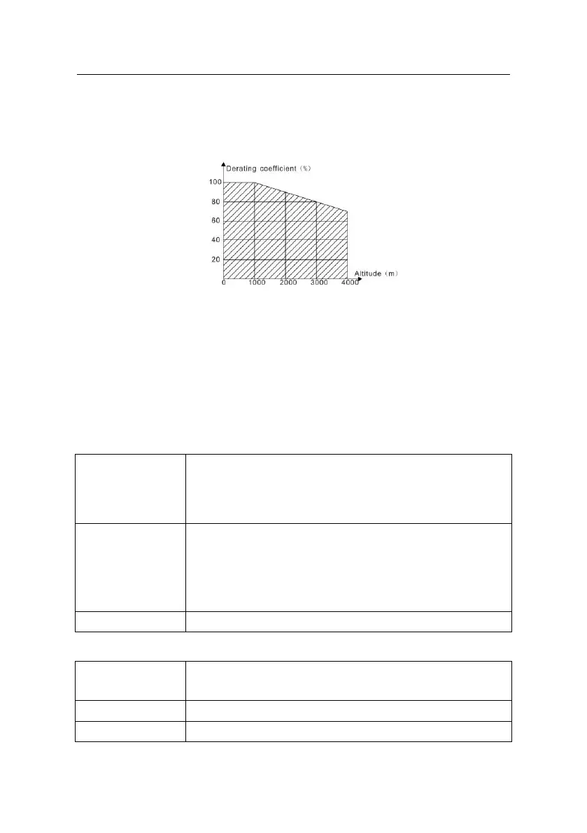
B.2.2.2 Altitude derating
The device can output rated power if the installation site below 1000m. The output power
decreases if the altitude exceeds 1000 meters. Below is the detailed decreasing range of the
derating:
For 3-phase 200 V drives, the maximum altitude is 3000 m above sea level. In altitudes
2000…3000 m, the derating is 2% for every 100 m.
B.2.2.3 Carrier frequency derating
For Goodrive35 series inverters, different power level corresponds to different carrier
frequency range. The rated power of the inverter is based on the factory carrier frequency,
so if it is above the factory value, the inverter needs to derate 10% for every additional 1 kHz
carrier frequency.
B.3 Grid specifications
AC 3PH 380V(-15%)~440V(+10%)
AC 3PH 380V(-10%)~550V(+10%)
AC 3PH 520V(-15%)~690V(+10%)
Maximum allowed prospective short-circuit current at the input
power connection as defined in IEC 60439-1 is 100 kA. The drive is
suitable for use in a circuit capable of delivering not more than 100
kA at the drive maximum rated voltage.
50/60 Hz ± 5%, maximum rate of change 20%/s
B.4 Motor connection data
Asynchronous induction motor or synchronous permanent magnet
motor
0 to U1, 3-phase symmetrical, Umax at the field weakening point
The motor output is short-circuit proof by IEC 61800-5-1

 Loading...


