Goodrive35 inverters Basic operation instruction
231
Detailed instruction of parameters
Simple PLC 8~15 step
ACC/DEC time
Digital input function
selection
16:Multi-step speed terminal 1
17:Multi-step speed terminal 2
18:Multi-step speed terminal 3
19:Multi-step speed terminal 4
20:Multi-step speed pause
Simple PLC and the current
step of the multi-step speed
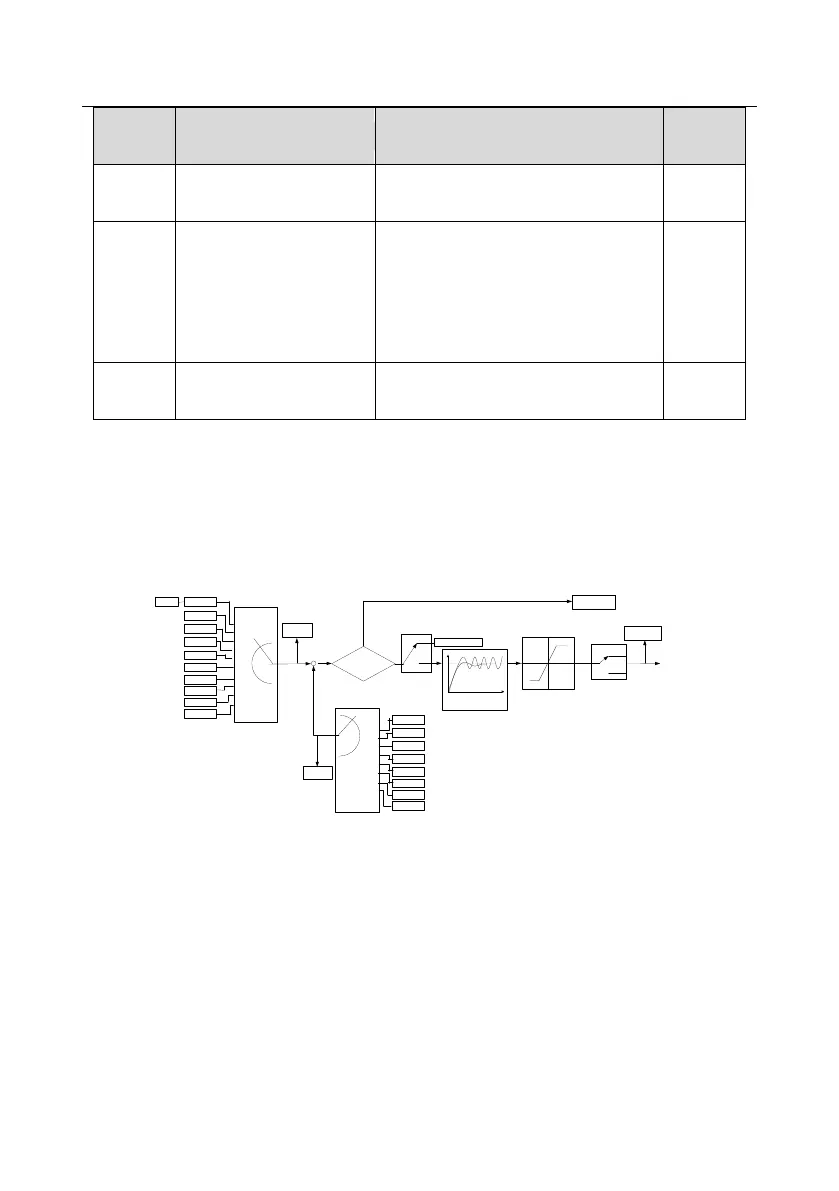
7.15 PID control
PID control is commonly used to control the procedure through the controlled procedure. Adjust the
output frequency by proportional, integral, differential operation with the dispersion of the target
signals to stabilize the value on the target. It is possible to apply to the flow, pressure and
temperature control. Figure of basic control is as below:
+
-
Given -feedback<P09.08(
P09.10
( lower limit of PID output (
P09.09
( the upper limit of PID output (
0
1
P09.03
( the chrematistic of PID output (
PID output
P17.00
P17.23
P09.08( PID control deviation limit(
P09.02
( PID feedback source selection (
P09.00
( PID given source selection(
P17.24
PID feedback
value
PID given value
Set frequency
0
1
2
3
4
5
6
7
8
9
Keypad
AI1
PROFIBUS
MODBUS
Multi-stage speed
HDI
AI3
AI2
Ethernet
CAN
0
1
2
3
4
5
6
7
AI1
PROFIBUS
MODBUS
HDI
AI3
AI2
Ethernet
CAN
Y
N
PID stop adjustment
Keypad setting PID given
Keep the current
frequency
Terminal function 25
PID control pause
Valid
Invalid
Kp P09.04(proportional gain)
Ti P09.05( integral time (
Td P09.06( differential time(
P09.01
Simple illustration of the PID control operation and adjustment:
Proportional adjustment (Kp): when there is an error between the feedback and the reference, a
proportional adjustment will be output. If the error is constant, the adjustment will be constant, too.
Proportional adjustment can respond to the feedback change quickly, but it can not realize non-fault
control. The gain will increase with the adjustment speed, but too much gain may cause vibration. The
adjustment method is: set a long integral time and derivative time to 0 first. Secondly make the
system run by proportional adjustment and change the reference. And then watch the error of the
feedback signal and the reference. If the static error is available (for example, increasing the
reference, the feedback will be less than the reference after a stable system), continue to increase the

 Loading...


