Goodrive35 inverters Installation guidelines
29
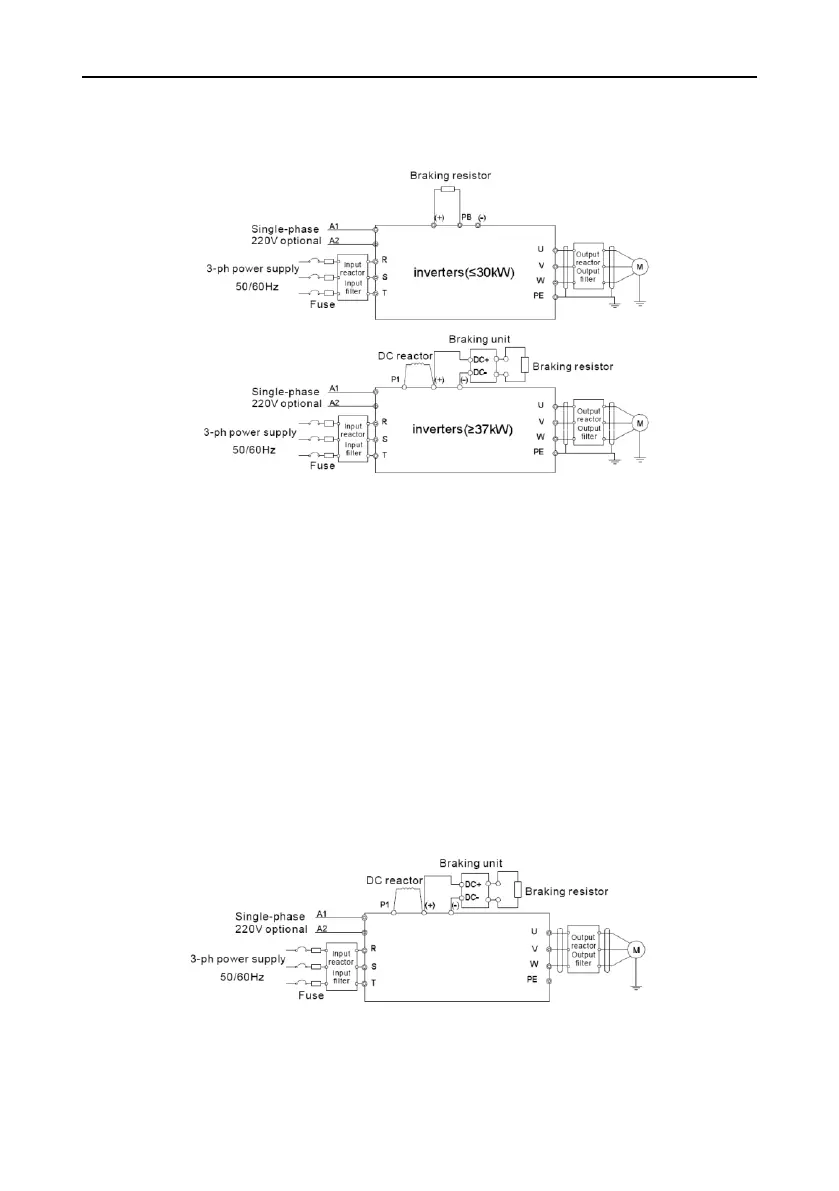
4.3 Standard wiring
4.3.1 Connection diagram of main circuit for the inverters of AC 3PH 380V (-15%)~440V(+10%)
Fig 4-7 Connection diagram of main circuit for the inverters of 380V
Note:
The fuse, DC reactor, braking unit, braking resistor, input reactor, input filter, output reactor,
output filter are optional parts. Please refer to Peripheral Optional Parts for detailed
information.
A1 and A2 are optional parts.
P1 and (+) are short circuited in factory for the inverters of 380V (≥37kW), if need to connect
with the DC rector, please remove the contact tag between P1 and (+).
Before connecting the braking resistor cable, remove the yellow labels of PB, (+), and (-) from
the terminal blocks. Otherwise, poor connection may occur.
4.3.1.2 Connection diagram of main circuit for the inverters of AC 3PH
520V(-15%)~690V(+10%)
Fig 4-8 Connection diagram of main circuit for the inverters of 660V
Note:

 Loading...


