Goodrive35 inverters Keypad operation procedure
47
Keypad operation procedure 5
5.1 What this chapter contains
This chapter contains following operation:
• Buttons, indicating lights and the screen as well as the methods to inspect, modify and
set function codes by keypad
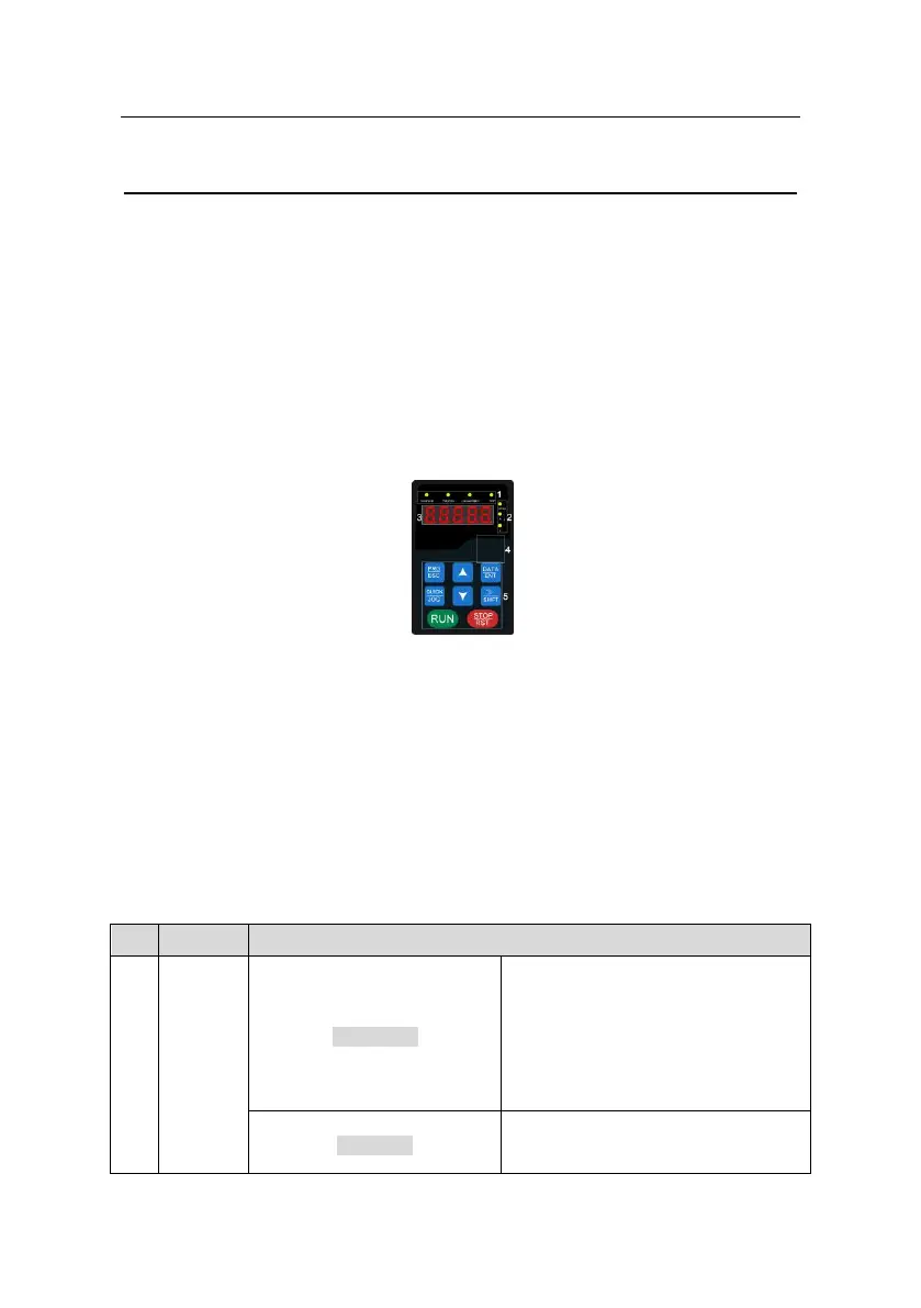
5.2 Keypad
The keypad is used to control Goodrive35 series inverters, read the state data and adjust
parameters.
Fig 5-1 Keypad
Note:
1. The LED keypad is standard but the LCD keypad which can support various languages,
parameters copy,10-line displaying is optional and its installation dimension is compatible
with the LED keypad.
2. It is necessary to use M3 screw or installation bracket to fix the external keypad. The
installation bracket for inverters of 380V 1.5~30kW is optional but it is standard for the
inverters of 380V 37~500kW and the inverters of 660V.
LED off means that the inverter is in the
stopping state; LED blinking means the
inverter is in the parameter autotune
state; LED on means the inverter is in
the running state.
FED/REV LED
LED off means the inverter is in the

 Loading...


