Goodrive35 inverters Appendix D
333
Note:
1. The rated derate voltage of the input reactor is 2%±15%.
2. The power factor of the input side is above 90% after installing DC reactor.
3. The rated derate voltage of the output reactor is 1%±15%.
4. Above options are external, the customer should indicate when purchasing.
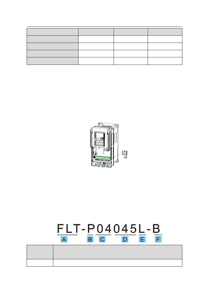
D.7 Filter
Goodrive35 series inverters have embedded C3 filters which can be connected by J10.
Note: Do not connect C3 filters in IT power system.
The input interference filter can decrease the interference of the inverter to the surrounding
equipments.
Output interference filter can decrease the radio noise cause by the cables between the
inverter and the motor and the leakage current of the conducting wires.
Our company configured some filters for the convenient of the users.
D.7.1 Filter type instruction
FLT:inverter filter series

 Loading...


