EasyManuals Logo

INVT Goodrive 35 Series User Manual

INVT Goodrive 35 Series
344 pages
To Next Page IconTo Next Page
To Previous Page IconTo Previous Page
Page #322 background imageLoading...
Page #322 background image
Goodrive35 inverters Appendix D
321
Peripheral options and parts Appendix D
D.1 What this chapter contains
This chapter describes how to select the options and parts of Goodrive35 series.
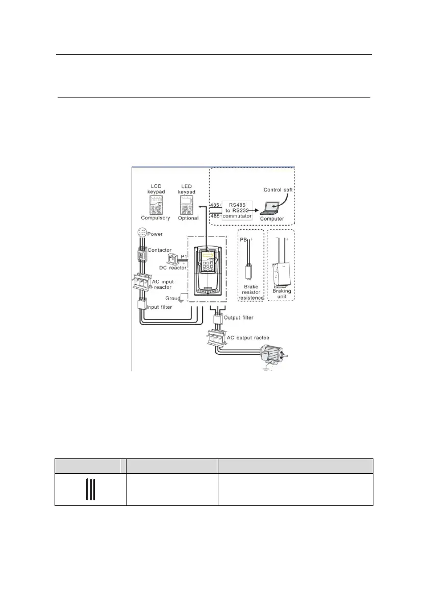
D.2 Peripheral wiring
Below is the peripheral wiring of Goodrive35 series inverters.
Note:
1. The inverter of 380V (≤30kW) are embedded with braking unit.
2. The inverters of 380V (≥37kW) and of 660V have P1 terminal and are connected with
external DC reactors.
3. The braking units apply standard braking units. Refer to the instruction of DBU for detailed
information.
Pictures
Name
Descriptions
Cables
Device to transfer the electronic signals
www.barghmaher.ir

Table of Contents

Questions and Answers:

Question and Answer IconNeed help?

Do you have a question about the INVT Goodrive 35 Series and is the answer not in the manual?

INVT Goodrive 35 Series Specifications

General IconGeneral
BrandINVT
ModelGoodrive 35 Series
CategoryInverter
LanguageEnglish

Related product manuals