Goodrive35 inverters Basic operation instruction
235
Detailed instruction of parameters
Detection time of
feedback offline
0x000~0x111
LED ones:
0:Keep the integral adjustment ON while
the frequency achieves upper or lower
limit.
1:Stop the integral adjustment while the
frequency achieves the upper or lower
limit
LED tens:
0:The same with the setting direction
1:Opposite to the setting direction
LED hundreds: when P00.08 is 0
0: Limit to the maximum frequency
1: Limit to A frequency
0.00Hz~P00.03 (the Max. frequency)
7.16 Commissioning for special functions
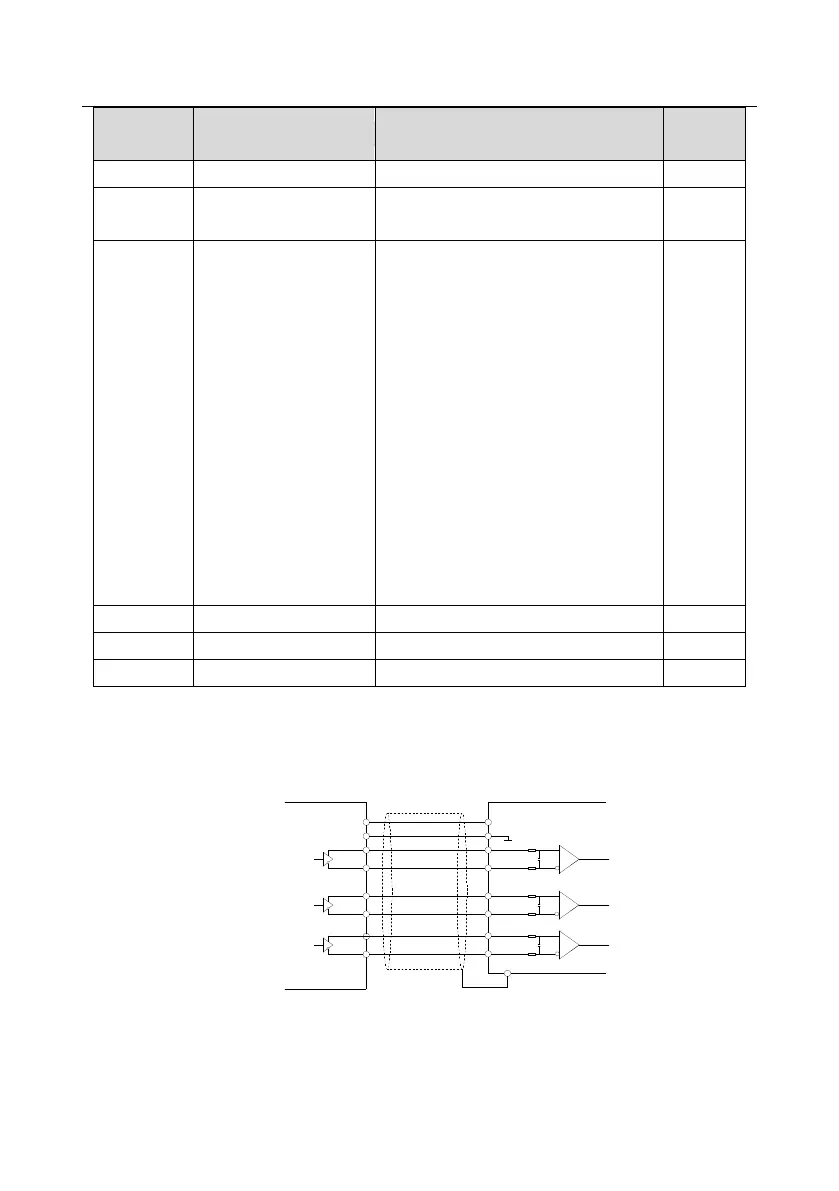
7.16.1 Wiring mode of the encoder and pulse reference terminal
1. Differential output (suitable toC1, H1 and H2)
B+
A+
B -
B +
A -
A +
GND
5V
PE
VCC
0 V
A-
B-
A
Use shield cables
Differential
output
Z -
Z+
Z+
Z-
B
Z
Note: The diagram of differential output is given to the H1 interface, C1 Iinterface applies
opto-isolator and H2 interface applies differential chips. The external wiring is the same as that of

 Loading...


